Continue to Site

Eng-Tips is the largest engineering community on the Internet

Intelligent Work Forums for Engineering Professionals

  • Congratulations SSS148 on being selected by the Eng-Tips community for having the most helpful posts in the forums last week. Way to Go!

"Partial" Block Shear Failure 2

Status
Not open for further replies.

phamENG

Structural
Feb 6, 2015
7,600
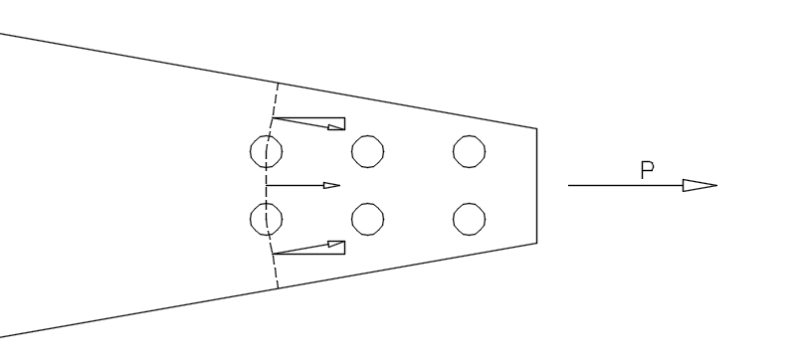
In a gusset plate connection for a tension member in which the gusset is particularly long and/or narrow (typically a tapered gusset) can have what I have found in some literature to be called a "partial block shear" limit state. Intuitively, it makes sense. In traditional block shear, you have orthogonal shear rupture and tension yield or rupture planes and the block shear capacity is the sum of the strengths of those planes (per J4.3, AISC 360-10). But if the gusset tapers quickly, you could end up with an inclined failure plane from the bolts at the end of the tension member or weld to a point along the gusset (the inclined failure plane would be orthogonal to the free edge of the gusset rather than the line of force from the tension member).

Does anyone have any good, practical guidance on calculating the allowable strength in such a connection? The only real suggestion I've found in searching through literature online has been to apply the staggered bolt modification to net area from B4.3b (s2/4g), but they don't provide any evidence to back it up (theoretical justification or empirical results).

My thought is this: find the projected length of each leg of the partial shear failure on a line perpendicular to the line of force, and then determine a uniform linear distribution across each leg. Take that distribution and separate it back into the orthogonal components of the failure plane (shear and tension acting on that plane). Then, the equation from the manual would change to be something more like this: Rn=sum(0.60FuAnv)+sum(FuAnt). I'm not considering the tensile yield here as comparing the combined and then re-separated tension and shear stresses to different failure criteria seems flawed. This neglects relative stiffness of the various lines, but that seems ok as the size is relatively small and localized yielding to redistribute stresses is not altogether uncommon in these sorts of connections. A sketch is below - hopefully it helps to clarify.

Thanks. (For the record, I'm writing a spreadsheet to aide in the design and analysis of new or existing braced frame gusset connections, and I'm reviewing the various configurations I may consider or encounter...this is just one I haven't had to deal with much and would like to get some other opinions.)

taperedgusset_anwwgv.png
 
Replies continue below

Recommended for you

The taper angle would have to be much steeper than what you've shown before I would consider it to be anything but a straight tension fracture along the dashed line, just as you've shown it. With the angle you've shown, the shear resistance component would be negligible, and it wouldn't get much bigger until the angle was huge. Until the angle for the taper exceed 25 or 30 degrees, it would be only slightly conservative to ignore the shear component, which is what I would do, even for a design aid spreadsheet.

That said, I would consider the S2/4g a valid way to evaluate the resistance, provided you're using the projected dimensions parallel and perpendicular to the direction of the applied force.

Rod Smith, P.E., The artist formerly known as HotRod10
 
Rod - Thanks. Do you know where the s2/4g comes from? I know it's empirical, but I don't see where AISC provides a reference for the research. I'd like to read the source paper before relying on it for something outside of what the established practice seems to indicate.

If I may trouble you to do so, can you provide any comments on the method I suggested? I'm curious to see if anyone finds fault with it either fundamentally (it's just plain wrong) or practically (insufficient conservatism, for example).
 
I think it was derived mathematically for shortest distance of staggered holes in net effective area calculation, on direct tension.

In my opinion, your plate lack of meat on T/B sides to develop required mechanism for transferring shear, you don't have the block shear problem, but a plate subjects to direct tension, which is resisted by strength of net effective area.
 
retired - Thanks. Based on what I've found, it's added back into the net area calculation to account for the effect of combining tension and shear stresses in a non-orthogonal plane between staggered bolt holes based on observed performance of those types of connections. It does sound as though it could be applicable here, but I can't find enough data to make me feel really good about it beyond its use as provided for in the spec.

By the way, that's not a real gusset plate, just an illustration. I'm looking at a general case, not a specific design problem.
 
I understand that was jut a bait for idea. As your understanding is correct, the failure mechanism of this type of connection was based on observation over tests, then formulized conservatively. Due to uncertainty in stress distribution over plate having irregular shape, we, so far, can only follow/obey the established rules.
 
I think retired13 makes a good point regarding the lack of confinement for shear at the free edge of the plate, so I have to withdraw my previous statement that the S2/4g was valid; it may not be for what you're doing. Without that, I haven't seen anything, theoretical or empirical, that would indicate how to sufficiently quantify the shear component of the capacity. If I was doing it, I would assume the failure plane as you've shown, and use the projected width perpendicular to the line of applied force as tension area and call it a day.

If the scale of use is large enough to justify the expense, you could have some testing done on some representative samples to failure (fracture), to see where and how they break. Maybe it's been done, but not that I've come across.

Edit: The AASHTO spec. provides this in the commentary -

"The development of the “s2/4g” rule for estimating the effect of a chain of holes on the tensile resistance of a section is described in McGuire (1968). Although it has theoretical shortcomings, it has been used for a long time and has been found to be adequate for ordinary connections.

In designing a tension member, it is conservative and convenient to use the least net width for any chain together with the full tensile force in the member. It is sometimes possible to achieve an acceptable, slightly less conservative design by checking each possible chain with a tensile force obtained by subtracting the force removed by each bolt ahead of that chain, i.e., closer to midlength of the member from the full tensile force in the member. This approach assumes that the full force is transferred equally by all bolts at one end."

Rod Smith, P.E., The artist formerly known as HotRod10
 
In designing a tension member, it is conservative and convenient to use the least net width for any chain together with the full tensile force in the member.

This exactly what in my thought. The stress is highest in the front row of bolts, thus so felt by the plate, but we don't know exactly where (how far into the chin of holes) the stress is exhausted, I highly suspect the bolts and plate farther from the load have much contribution to strength, as the stress has diminished, although we simplify all bolts share the same proportion of the force. But it is beyond our knowledge at this point. Maybe a FEM study can provide more insight though.

Rod, you slapped my face for credit you a star. I can't/won't retract it, only to point out that, somehow, you made a mistake by overthinking, since you were correct in the first place.
 
Thank you both for your valuable insights. And thanks for the AASHTO commentary reference - I don't currently have access to it.

Unless anyone else comes in with additional information, I'll shelve this one for now and go with the pure tension approach using the area perpendicular to the force passing through the points where the failure plane(s) cross the boundary of the gusset. As you both said, this is a conservative approach so long as the angle is reasonable.


retired13 said:
Rod, you slapped my face for credit you a star. I can't/won't retract it, only to point out that, somehow, you made a mistake by overthinking, since you were correct in the first place.

Thought I was agreeing with you, and that you were correct. My (revised) view is that what's applicable between holes is not necessarily applicable between a hole and the edge of the plate, particularly in regard to shear capacity. I don't really have a handle on the flow of the internal stresses, so I wouldn't want to recommend using the S2/4g without further investigation of how it was derived.

As far as the distribution of force to the bolts, when considering ultimate capacity of the connection (fracture of the net section), the plate is assumed to yield in a ductile manner before it reaches that point, so deformation of the plate is assumed to be adequate to distribute the load equally to all bolts, assuming the bolt holes are within the specified tolerances for size and placement.

Rod Smith, P.E., The artist formerly known as HotRod10
 
As you both said, this is a conservative approach so long as the angle is reasonable.

My recommended approach should become more conservative as the taper angle increases.

Rod Smith, P.E., The artist formerly known as HotRod10
 
You know, I don't think I agree it's necessarily conservative anymore. This is now just a pure tension check, but it uses the full width of the gusset. That's ok, as long as it's less than the width of the Whitmore stress block. If lw is less than that width, then it's actually unconservative. If the plate reaches yield in lw, then it will begin to deform plastically and the stress will increase toward the free edges. Eventually, it'll reach fu and tear. So, for standard geometry, I don't think the "partial block shear" would be a thing. Maybe for something really unique, but that would have to be checked carefully by hand in any case. Sorry about that...
 
Rod,

so deformation of the plate is assumed to be adequate to distribute the load equally to all bolts

That is classical answer found in the text, I'll leave my doubt under dirt. :)
 
If you take the shortest distance from the bolt hole to the edge of the plate (as shown in the OP's sketch) and use only the projected length of that line perpendicular to the line of force, the result should be conservative, since it ignores any contribution to the capacity from shear.

Rod Smith, P.E., The artist formerly known as HotRod10
 
Right, but if that width is wider than the Whitmore stress block (lw), then your area is too large. And if it's less than lw, it doesn't matter anyway because it would be picked up in that check.

 
You may be right, phamENG. I'm not familiar with the Whitmore approach to the analysis, but I wonder whether it's applicable to the analysis of a plastic section.

Rod Smith, P.E., The artist formerly known as HotRod10
 
There is an FHWA document for analyzing gusset plates. If I can find the link I will post it.
 
Thanks, Rick. Looks like it pretty well confirms where we left off.
 
Status
Not open for further replies.

Part and Inventory Search

Sponsor