Continue to Site

Eng-Tips is the largest engineering community on the Internet

Intelligent Work Forums for Engineering Professionals

  • Congratulations IDS on being selected by the Eng-Tips community for having the most helpful posts in the forums last week. Way to Go!

"Waviness" in elements in Abaqus Explicit

Status
Not open for further replies.

luc46552

Mechanical
Jun 13, 2019
13
Hello all,

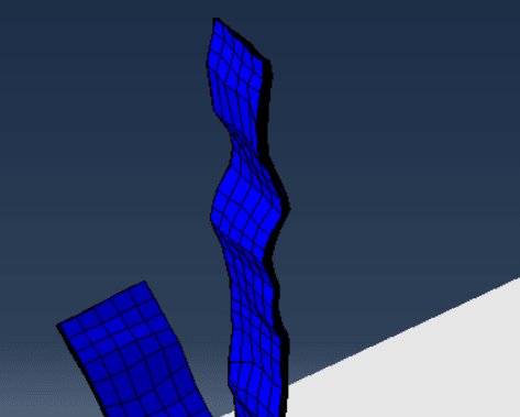
I am trying to model a dynamic model in Abaqus Explicit. It is an assembly made of multiple parts that begin moving from rest. It starts out fine, but as the parts' velocities begin to increase, the elements develop "waves", or distortion that looks like waves shown below. This eventually causes the simulation to abort. Does anyone have any clue why this may be happening?

Element Type: C3D8R
Hourglass Control: Enhanced
Contact Initialization: Treat as Interference Fit

Material Properties: Wood (E = 6.9e9 Pa)

Initially moving, there's no distortion:
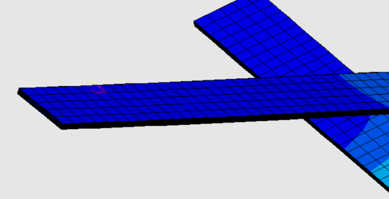
Image1_kbruol.png


Once it gets going, this happens:
Image2_cjjekm.png


Worth noting: The Explicit, Dynamic analysis is made from an assembly and a predefined field imported from an Standard, Static analysis using a python script.
 
Replies continue below

Recommended for you

Can you attach more pictures showing these parts with boundary condition and load symbols ? How are they moving and what’s the time step ?
 
Sure,

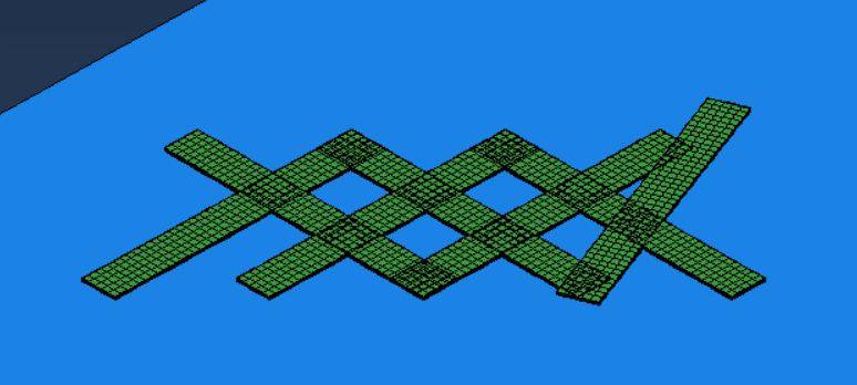
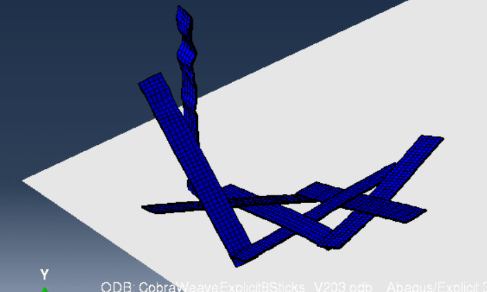
The assembly consists of a number of parts with opposing contact constraints. In the dynamic, explicit simulation, the parts are imported from a previous static analysis along with a predefined field. This is done by using python to grab the assembly and import the predefined field from the Abaqus, standard ODB file. Here is the assembly without the field:
StructureExample_npobmg.png


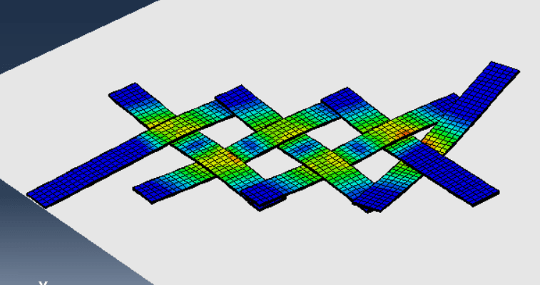
Here is step zero of the dynamic step:
Step1_yca2an.png


Step 1 of the dynamic step:
Step2_v2ji2b.png


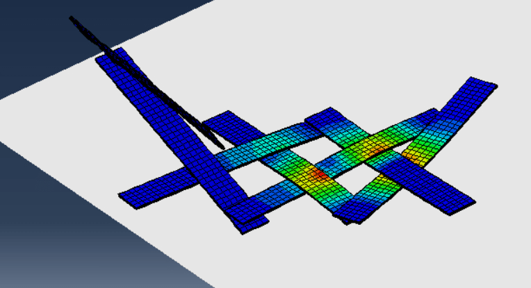
Step 4 of the dynamic step before it aborts:
Step3_rklybz.png


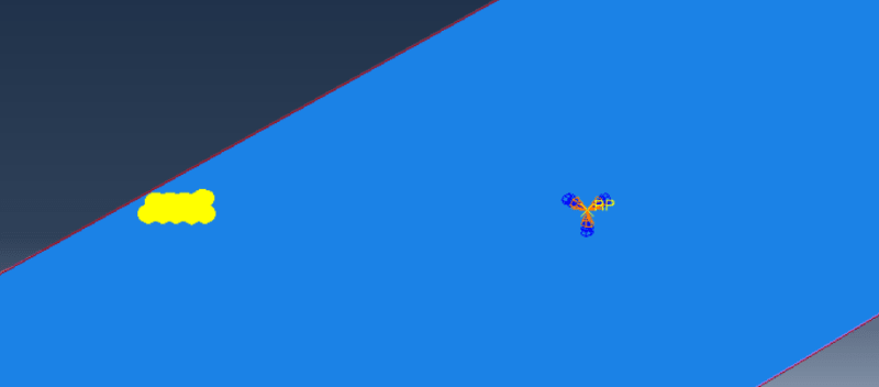
In the dynamic, explicit step, general contact is used with surface overclosure and a coefficient of friction. The same contact is used between the flat ground and the parts, as well as between the individual parts themselves. The only BC used is to fix the ground in place, which is an analytical rigid body. This is shown below for reference. It's pretty simple, just a displacement BC set to zero:
BCExample_bzzjna.png


There is also a constant downward acceleration of -9.8 m/s^2 applied to the entire assembly. Since the structure is not net zero, the parts force each other apart and convert their stored strain energy into kinetic energy. Since this is dynamic, explicit, the time scaling factor is set to 1, and the time increment is set to 'Automatic'. I do not believe there is a time step option, since that is only in Abaqus Standard.

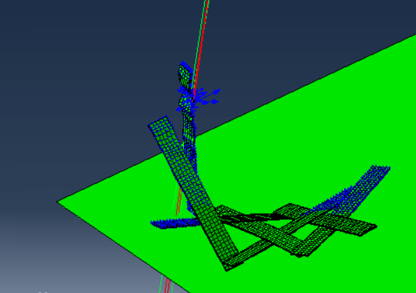
To give you an idea of movement, a velocity vector plot for step 4 is shown here. You can see that the loose part is moving much more quickly than the rest of the assembly. I was wondering if the quick acceleration of the part may have something to do with the distortion in step 4, but I'm not sure.
VelPlot_wla9kh.png
 
Actually, I meant step time (time period of the step).

Do these parts overlap initially ? This may cause problems - contact may not work properly in this case.
 
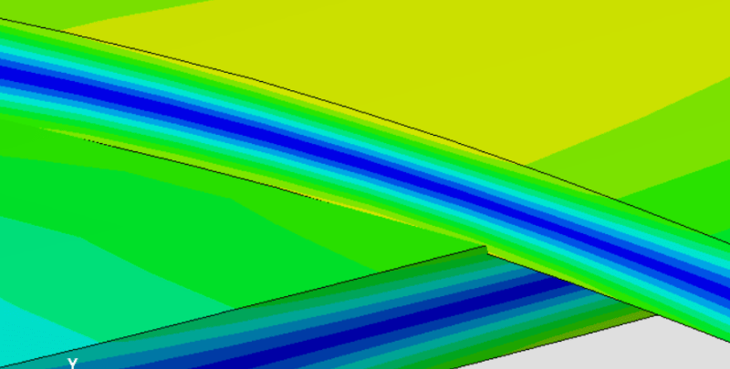
I see, there does seem to be some small amount of overlap between the surfaces in frame zero (shown below).
Overlap_hjggt3.png


The step time is set to 0.3. This was an arbitrary decision on my part, since I need to see some significant amount of detonation but I can't let it run for three days. Does the length of the step time affect the stability of an explicit simulation?
 
Status
Not open for further replies.

Part and Inventory Search

Sponsor