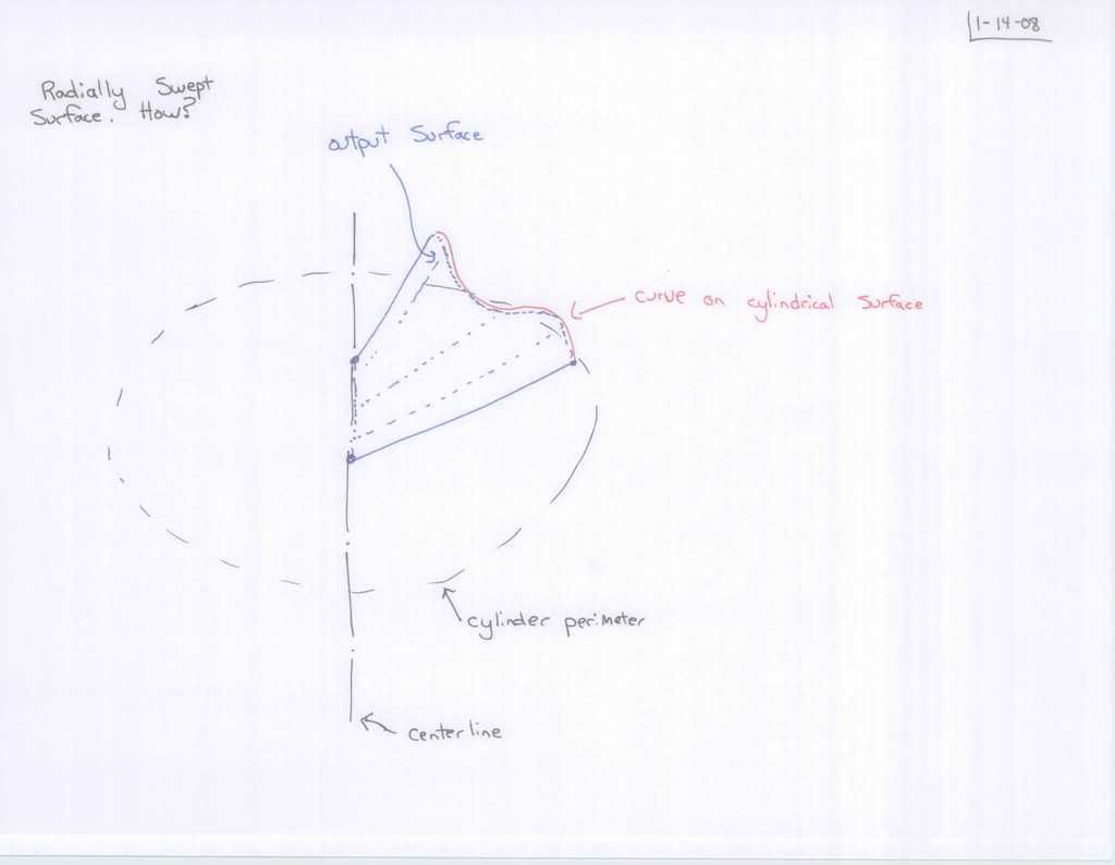
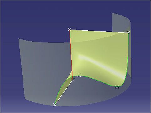
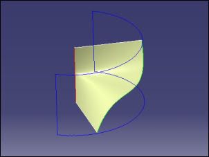
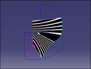
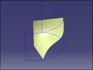
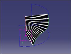
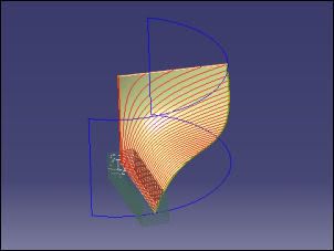
As is often the case there's more than one way to make this surface. I've tried some of them and here's the results. Apart from one, they
looked identical but when analized there are small differences in
area. If the first one is considered as having unit area then the others are:
(1) Blend - Curve, Curve Area = 1.000
(2) MSS - Section, Section Area = 0.996
(3) MSS - Section, Section, Guide, Guide Area = 0.970
(4) FreeStyle - Auto and Approximated Area = 0.999
(5) Fill - Four Boundaries Area = 1.007
When I first read this post my initial thought was that it was going to end up a ruled surface, which can be envisaged as an infinite number of equal length lines radiating from the axis out to the curve on the cylindrical wall. Being a ruled surface it is also the simplest mathematically, but when I thought more about it I realised that was nonsense - because of the cubic type spline laid on the cylinder to emulate the pencil sketch. As the spline has an inflection point the ruling lines would climb the axis and plunge before going up again - and this would result in an sharp ridge near the axis. Using those lines in construction would give an anticlastic surface of no use.
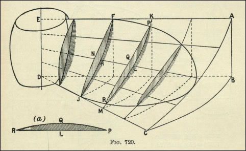
At the back of my mind had been something in one my old books: the strickling of sand done by mouldmakers when constructing the helical surface of a ship's screw propeller. A board, that could slide axially and swing on a vertical pole (DE), followed a curved template (ABC), sweeping the sand as it moved.
From
Practical Geometry and Graphics (D A Low, 1929)
The Blend was the first one I tried, followed by an unguided MSS one which had bowed edges - so that it was more at ease with itself; but at the same time the bows would probably make it not practical. The guided MSS one was
almost identical to the Blend - but required the construction of two linear guides. These are implicit in a Blend between two elements.
The FreeStyle Blend (both Auto and Approximated) was as expected; almost the same as the GSD Blend - there's nothing in it really. The Fill version was done to illustrate yet another way of doing it, but I'd be careful with Fill, it can lead to messy solutions. In the end it's obviously up to the user to decide which is the best - only the user knows exactly what is required.
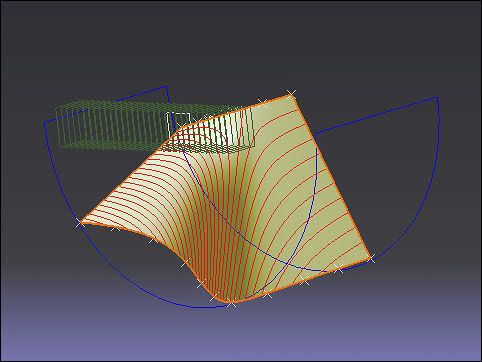
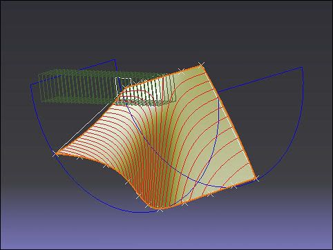
Sweep would not accept the inflection case, as it meant a reversal of axial direction. After adjusting the height of the two internal points of the original cubic (on the cylinder) Sweep gave a result - which had a pinched area halfway up the axis and a shelf-like area out towards the cylinder wall. The pictures below compare the Sweep and a Blend made from the same given geometry. Once again the Blend gave the better surface - this time by far.
Surface made using the Sweep tool
Surface made using the Blend tool
Compare the two cases when the Cutting Planes are in this orientation...
Sweep Blend
The first solution will not always be the best - but in this case I think it is, because the Blend gave the better result. The guided MSS was a close runner-up, but needed some construction work.
These are all done in FreeStyle with identical ACA Highlight settings.
Click them to enlarge...
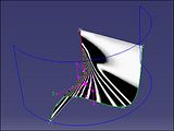
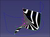
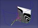
(1) (2) (3)
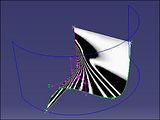
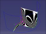
(4) (5)
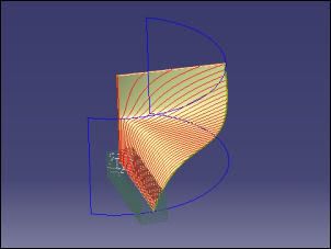
Area is not the only difference in all these surfaces: the smoothness can be seen using the old-fashioned
waterlines method. I've used the Cutting Planes tool in FS but it can be done manually in GSD.
This picture is of the Blend (1) but also applies to (3) and (4)
This shows the bowed sides of the unguided Multi-Sections Surface
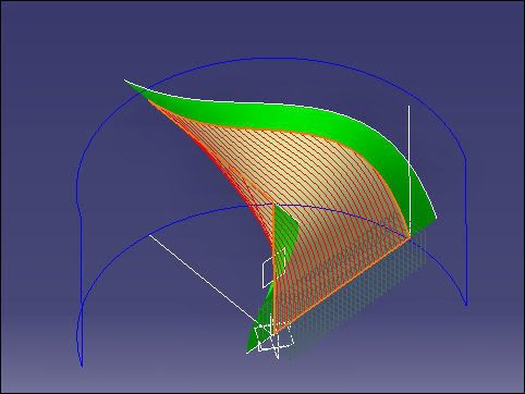
So far the Blend tool has been used at the most elementary level: from one curve to another. In this case there are no Supports to work with, but they could be constructed (green). This is a rather simple surface that we're after, I tried using two supports but there was no appreciable gain.
Photobucket has an Resizing tool...
