Materofact
Civil/Environmental
not sure why my brain is being thrown for a loop about this. this is why i like trusses by others...
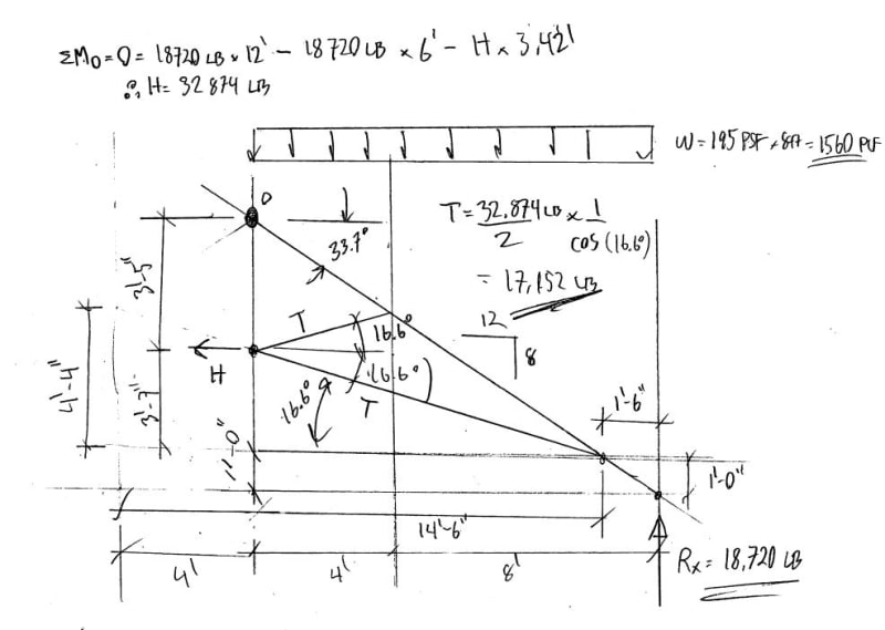
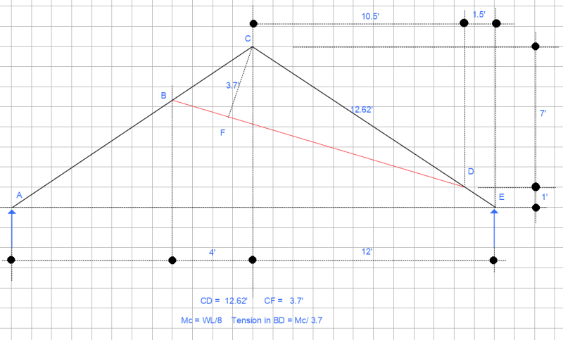
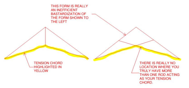
Please see attached picture. basically, an architect wants this look (ya...architects)...... 2 cables for each rafter criss crossing. However, 165 lb factored snow load and 30# dead load per foot on a 24' wide room. Architect wants 8 foot between the rafters! (perpendicular framing between). 8/12 pitch, upper attachmnet of cable is about 4 foot horizontal distance from the ridge.lower attachment is about 1 foot above the plate hieght.
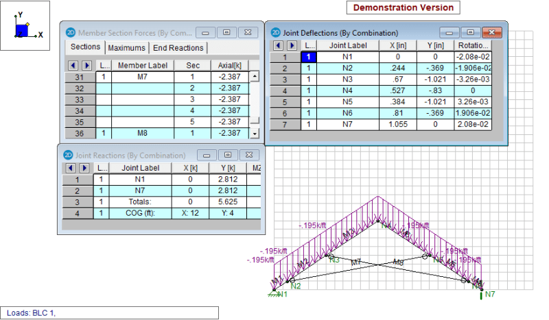
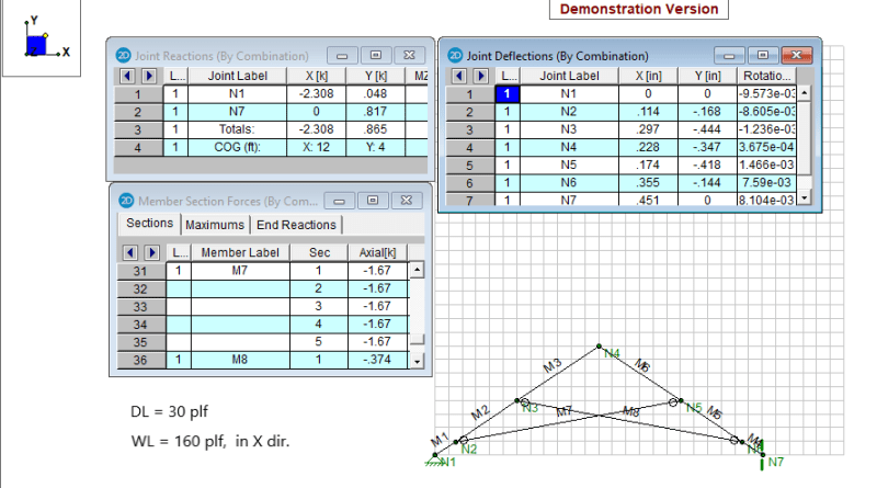
simple calcs (and strucalc type) analysis shows 16k for a typical rafter tie tension at both ends for a connection about 1 foot above the plate, *a little more when you resolve the angled connections.....but with TWO cables the connection should be half of a single member? 10x18 rafters is what i come up with, and about 9kk bolt reqauired connections into the wood. rafters need be designed for the cable loads in addition to the snow and dead, ofcourse. seems huge..?? AND...What about wind thrust INWARD? does roof diaphgragm take care of that once you get it up into the rafter?? how bout stiffening up the ridge joint with a bolted steel gusset?
Please see attached picture. basically, an architect wants this look (ya...architects)...... 2 cables for each rafter criss crossing. However, 165 lb factored snow load and 30# dead load per foot on a 24' wide room. Architect wants 8 foot between the rafters! (perpendicular framing between). 8/12 pitch, upper attachmnet of cable is about 4 foot horizontal distance from the ridge.lower attachment is about 1 foot above the plate hieght.
simple calcs (and strucalc type) analysis shows 16k for a typical rafter tie tension at both ends for a connection about 1 foot above the plate, *a little more when you resolve the angled connections.....but with TWO cables the connection should be half of a single member? 10x18 rafters is what i come up with, and about 9kk bolt reqauired connections into the wood. rafters need be designed for the cable loads in addition to the snow and dead, ofcourse. seems huge..?? AND...What about wind thrust INWARD? does roof diaphgragm take care of that once you get it up into the rafter?? how bout stiffening up the ridge joint with a bolted steel gusset?