Continue to Site

Eng-Tips is the largest engineering community on the Internet

Intelligent Work Forums for Engineering Professionals

  • Congratulations MintJulep on being selected by the Eng-Tips community for having the most helpful posts in the forums last week. Way to Go!

rafter tie height offset

Status
Not open for further replies.

balmores

Civil/Environmental
Jul 20, 2023
2
[URL unfurl="true"]https://res.cloudinary.com/engineering-com/image/upload/v1689898229/tips/rater_tie_height_offset_zv7g9i.pdf[/url]
Hello,
I'm working on a design to reinforce the roof structure of an old retiree friend’s house that suffered structural damage due to recent heavy snowstorms. The attached sketch shows a cross section of the rafter tie connection on a portion of the house. There is a 44" height offset created by a cripple or knee wall. The challenge I’m having is determining what would be the best engineering practice to resolve the thrust reactions of the rafters. Would it be practical to design a plywood connection or lap the existing rafters/ceiling joist to make the typical rafter tie connection? Please know that I'm not a structural engineer and I would appreciate any feedback and or suggestions.
The roof pitch is 6:12, 2x10 RRs at 2’oc, 2x6 CJs at 16” oc.

 
Replies continue below

Recommended for you

First off, you (or your friend) should hire a local structural engineer for the project. Refer to the following comments in case they may be of use to you or your engineer:
[ol 1]
[li]Normally, what I do to resist the outward thrust is to lap the roof rafters with the ceiling joists and design a connection to resist that force. In your case, this would be the connection at the 1251# reaction, per your diagram. Your case is a little trickier because the rafters and ceiling joists are at different spacings. Due to that, I might try to transfer the thrust force into the wall top plate and from there into the ceiling joists.[/li]
[li]For the other location, with the 720# force, as there seems to be another roof which is overframed there, I would try to design a connection relying on that other roof to resist the thrust.[/li]
[li]With all that said, I would question whether you really have the thrust forces indicated in the diagram. It seems that the struts that run from the interior bearing wall and support the rafters would provide enough vertical support for the rafters that the thrust would be minimal. It's difficult to provide a real assessment of this though without running an analysis accounting for the relative stiffness of the struts. For the sake of discussion though, if there was a sufficiently stiff and laterally braced strut supporting the peak and running down to that wall, or some other form of vertical support at the peak (like a structural ridge beam), I wouldn't expect any significant thrust.[/li]
[/ol]

How did you arrive at the thrust forces shown on the diagram?
 
If you ran this in a 2-D frame program, try releasing the left support horizontally and see if the roof is stable. It probably is and in that case I wouldn't worry about it.
 
Thank you both for the time in reviewing my question and providing your feedback. Much appreciated and I agree with your recommendations.
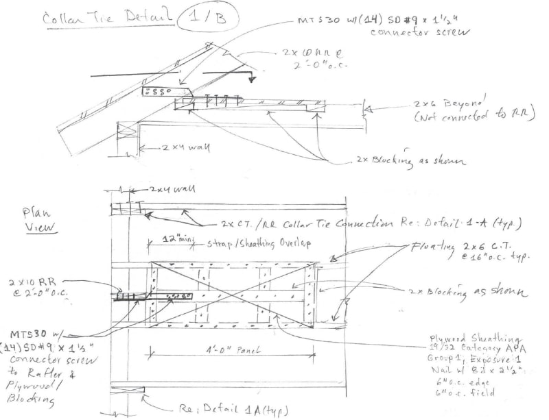
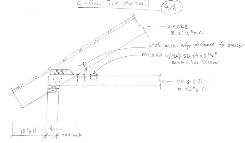
1. Please see diagram A and B which to my best knowledge was the best I could come up with. I never thought about using the top plate to CJ as a load path, very good suggestion!
2. Agree and I will consider it. Thank you!
3. Agree. I took a conservative approach and for simplicity assumed that the struts would provide vertical support and the thrust force would be resisted at the rafter tie connections.

I used Beyers 4th Edition example 2.6 to determine the thrust reaction using the local design snow load requirements, field conditions and assumption 2 above.

I will look into purchasing a 2D frame program as I don't have one.

Also, I thought about a designing a connection between the CJ and rafter bearing on the knee wall to resist the difference in forces. Any thoughts on this?''

Thank you both!
1A_ue4bve.jpg
1B_dwqoro.jpg
 
Those details seem reasonable in terms of resisting rafter thrust. They're nicely drawn as well. I've used similar details many times using the twist strap that you show.

If I'm interpreting Detail 1/A correctly, you would still have an issue due to the different spacings of the rafters and ceiling joists. Perhaps you're showing Detail 1/B to address that, though, in which case I think it makes sense.

For Detail 1/B, while what you show seems adequate off the top of my head, I would be more inclined to run a flat 2x on top of the ceiling joists positioned such that the twist strap nailing goes into it. This 2x (which might be a 2x8, 2x10, 2x12) would be attached to the top of each ceiling joist. If that can work for the thrust force, it would be a lot simpler to construct. If that doesn't work, though, then I would look at a solution more along the lines of what you show.

I still think the thrust force is probably small or negligible, but if there was thrust to be resisted, I think the way you're generally approaching it is correct.
 
Status
Not open for further replies.

Part and Inventory Search

Sponsor