Eng-Tips is the largest engineering community on the Internet

Intelligent Work Forums for Engineering Professionals

Railroad turntable support

Status
Not open for further replies.

spsalso

Electrical
Jun 27, 2021
942
0
0
US
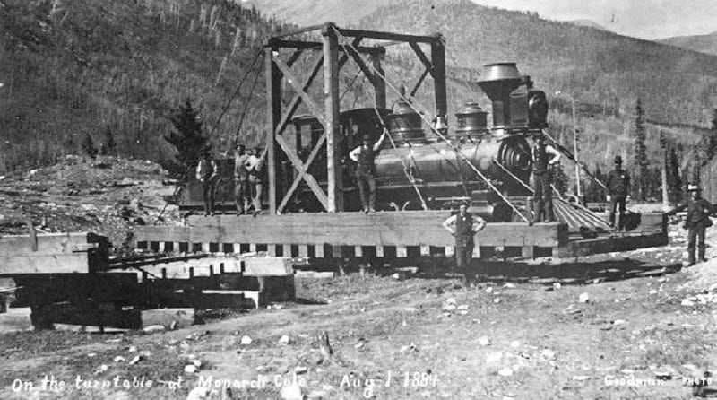
Railroad turntables support track that can be spun around to align with various radial trackage.

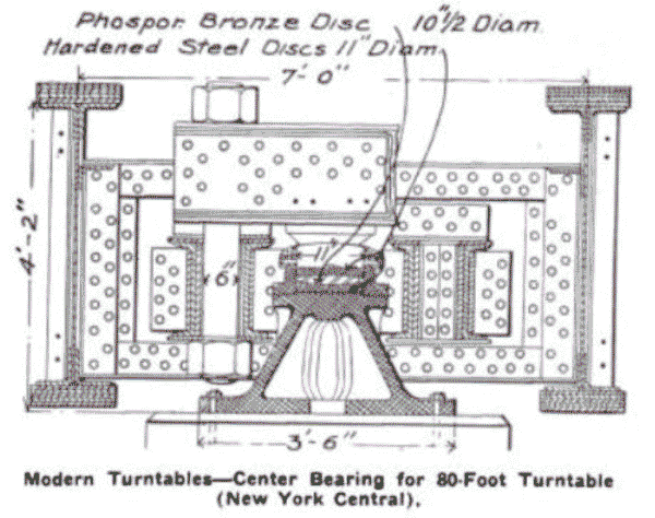
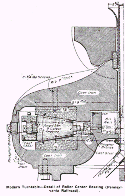
At first, they had only a center bearing. This meant that the locomotives had to be perfectly balanced before the turntable was turned (much like a swing bridge).

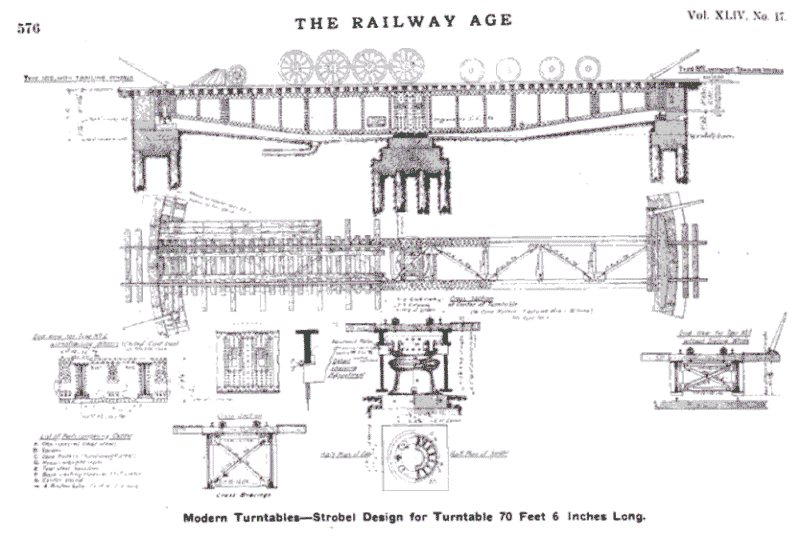
Fairly quickly, a ring rail was added out at the ends of the turntable bridge, along with wheels. Thus the need for perfect balance was eliminated.

My point of discussion: the bridge was then supported at three points: center and two ends. I found this odd, because the turntable bridge is "always" a single span (that is, there is no hinge in the middle). Thus there's a span supported at both ends and at the center.

That surprised me. It does appear that that design is indeterminate. I would have thought such a bridge would be supported only on the ends, with a non-loadbearing center pivot. But that appears to not be the case. I suppose this could be viewed as the use of "outriggers"--the outer bearings only being used when the bridge was out of balance. A problem with this is that those outriggers must support a huge load as locomotives move on and off the bridge. Being that sturdy, I do wonder at the use of a loaded center bearing at all.

Also, railroad turntables are turned by using electric motors on those wheels on the outer ends. They thus would HAVE to be loaded to get traction to turn the locomotive.


I'm finding this design odd, and am wondering what bridge people here think about it.


spsalso
 
Replies continue below

Recommended for you

Having a support in the middle shortens the span by half. the new ones with the ring may be on an elastomeric bearing, which will deflect under load and ensure the weight is distributed to the outside ring. It also doesn't take alot of traction to rotate one of those, since the acceleration is minimal.
 
"Having a support in the middle shortens the span by half."

True. But it would seem wise to design for the unfortunate day when only the ends of the table are loaded, thus doubling the span length. And once you've done that, why would you bother to design for loading in the middle?


"the new ones with the ring may be on an elastomeric bearing, which will deflect under load and ensure the weight is distributed to the outside ring."

Most railroad turntables were built roughly 100 years ago. They last about forever, and rarely need more than repair. Also, in the US anyway, there isn't a lot of new rail lines being built, so turntables are pretty much already where they're needed.

My point is that using an elastomeric bearing might well be a great solution, but I don't see it being implemented much.

Incidentally, I've see drawings of the center bearings. All the ones I saw were tapered roller, arrayed in what I think of as a vertical loadbearing pattern. I read also of plain bearings. I suspect those were used in lighter duty versions.


"It also doesn't take alot of traction to rotate one of those, since the acceleration is minimal."

Quite true. But steel wheels on steel rails need a certain amount of weight to transfer force from drive wheel to rail. That's why the weight of a locomotive is so important. In the extreme, if there was only 10 pounds of vertical load on the driven end of the table, the wheel would spin.

At least for one example I have in mind, there was a motor at each end. The extent of using twin motors is right now very much in question. For me. Was it "always" done? Occasionally done? I don't know, right now.


spsalso
 
...the unfortunate day when only the ends of the table are loaded, thus doubling the span length.

It doesn't work that way. If the ends only are loaded, then the supports at the ring are loaded, and the span across the middle carries nothing.

Most railroad turntables were built roughly 100 years ago.

Doesn't mean they couldn't retrofit it with an elastomeric bearing.

They last about forever, and rarely need more than repair.

Think about that for a minute, and then reread your original post.

Quite true. But steel wheels on steel rails need a certain amount of weight to transfer force from drive wheel to rail.

While the load of train engine may be centered over the center bearing, the loading pattern on what amounts to a 2 span continuous beam is out towards the middle to outer ends of the spans, where the wheels of the engine bear on the beam. The beam is not even close to being rigid. It bends and deflects, and distributes the load to all 3 support points, based on where the loads are on the beam.

Anyway, turntables are mostly for tourists now anyway. Modern train engines can and do run 'forward' or 'backward' just the same, so there's rarely, if ever a need for a turntable anymore.
 
Distribution of live load for 135' turntable:


Live_load--turntable_an6vdu.jpg


spsalso
 
Note that my loading example is 30 years later than the examples posted by SlideRuleEra.

They do show the typical design of 1907, I think.

From the 1907 documents:

"Such heavy weights and long wheelbases require very strong and stiff girders for the turntables..." NOT flexible.

"The rocking surfaces are so designed that the load must be symmetrically distributed under all conditions." This would mean that there would be no need for outer bearings or ring rails, since they would never be loaded.

And yet, there they are (railroads being notorious for spending money on silly little nothings).

Here is a drawing for a 1940 bridge:


[URL unfurl="true"]https://res.cloudinary.com/engineering-com/image/upload/v1681962011/tips/Dans_Drawings_013_tyngkt.pdf[/url]


spsalso
 
The wheel loads will be distributed to all 3 support points. The beams under the turntable would have to be much larger and heavier if it did not have a support in the center, and they apparently been working well for many decades.
 
<- no drive wheels at all
<- drive wheels aren't the support wheels. Not shown but I would expect a large spring to push the drive wheel against the weight of the bridge and any payload
<- another foot/hand turned turntable, though one comment indicates the small pit has a pedaled arrangement. I like the little bump from the mismatch in height plus the small gap.

Everything is flexible.
 
Everything is flexible.

...including the beam. This is the key. It's a 2 span continuous beam that bears on all 3 supports. With a typical engine all the way on the turntable, there will be nearly as much weight on the ends as the middle.
 
For the middle example in the three linked above, the drive wheel is one of four support wheels on one end. It's unclear to me if there's two motors or one. I'm leaning towards two--one on each end.

For most powered turntables, it appears the motors are fed 3 phase AC. In many photos, you can see the three wires connecting to the slip ring bridge, over the top of the turntable.

Here's another turntable video:


It's air powered. However, it still has the slip ring bridge, so it was converted at one time. Or perhaps they used an electric powered compressor for the air.

Here is a picture of a turntable without a ring rail:


turntable_without_ring_rail_kdpyxe.jpg


spsalso
 
Status
Not open for further replies.
Back
Top