Continue to Site

Eng-Tips is the largest engineering community on the Internet

Intelligent Work Forums for Engineering Professionals

  • Congratulations KootK on being selected by the Eng-Tips community for having the most helpful posts in the forums last week. Way to Go!

RBE2 or RBE3 for this application? 2

Status
Not open for further replies.

MrK159

Mechanical
Sep 17, 2014
30
Assume you have a plate with a rigid box attached to it by 4 screws. Using the location of center of mass of the box you place a node or 0d mass there, apply a load or other applied forces (direction doesnt matter). Would you use an rbe2 or rbe3 from the cg to the bolts?
 
Replies continue below

Recommended for you

If the box is made of rubber, I would put an RBE3.
If it is metallic, then I would put RBE2.

I'm assuming the plate rigid like plastic, metal or glass.

But if you are doing a modal analysis, you might wanna model more detail.

Spaceship!!
Aerospace Engineer, M.Sc. / Aircraft Stress Engineer
 
Hello!,
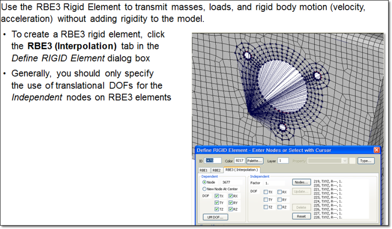
In general in such situations I will always use RBE3 elements. The RBE3 element is a powerful tool for distributing applied loads and mass in a model. Unlike the RBAR and RBE2 elements, the RBE3 doesn’t add additional stiffness to your structure. Forces and moments applied to reference points are distributed to a set of independent degrees of freedom based on the RBE3 geometry and local weight factors.

To learn more about rbe2 vs. rbe3 you can visit my blog in the following address:

rbe3_tjdss8.png


Best regards,
Blas.

~~~~~~~~~~~~~~~~~~~~~~
Blas Molero Hidalgo
Ingeniero Industrial
Director

IBERISA
48004 BILBAO (SPAIN)
WEB: Blog de FEMAP & NX Nastran:
 
I'll have to object to the above comment for some cases (but it may also be valid for some simple cases). Please see this other title you opened for this issue. I've made some more explanations there depending on your requirements:

Spaceship!!
Aerospace Engineer, M.Sc. / Aircraft Stress Engineer
 

As the OP mentioned "rigid box" in his post, the best representation of this is using a RBE2 from the cog of the box connected to the mounting points.

Usually using Tx,Ty and Tz as the dependent d.o.f's at the mounting points would suffice, unless you claim that the joint can carry moments.
 
Most times, especially when you are dealing with a slightly more advanced analysis than usual, you will come to understand that using RBE2s might be worst action to take no matter how rigid your mounting box is. I made some extra explanation on the above link mentioned. Please refer to that for additional explanation. Think twice before you ever use RBE2s. If the total stiffness of the box and the surrounding plate are at a ratio of 1 or 2, the RBE2 would not be correct. I can't pin-point an exact stoffness ratio, you have to understand the stiffnesses of your parts in an assembly to decide what to use. Hope this explanation also adds up to previous ones.

Spaceship!!
Aerospace Engineer, M.Sc. / Aircraft Stress Engineer
 
Status
Not open for further replies.

Part and Inventory Search

Sponsor