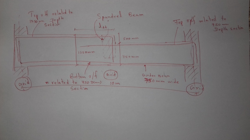
For a heavily loaded power station, A girder beam having a 500 mm set down is required to design(refer attachment). This girder is also supporting spandrel beam exactly at the set down location. The design procedure that I have followed for this non prismatic beam is as follows
1. The beam is modeled using frame element as a sub frame.
2. Two different frame elements are defined for the different two sections and they are combined using insertion points & thereafter loaded the beam
3. Analysis results are obtained and the bottom flexure r/f are derived using the 750 mm(D) dropped section & continue through out the bottom
4. Top r/f at restraint ends are also calculated for respective sections(1250 and 750 mm D)
5. Links are calculated from the analysis results at both ends for respective sections while provisions are made for the hanger links also
6. The Detailing is done as given in the attachment
Please comment if there are any more considerations on analyzing, designing and detailing to be done for these kind of beam sections
Thanks in advance


