Continue to Site

Eng-Tips is the largest engineering community on the Internet

Intelligent Work Forums for Engineering Professionals

  • Congratulations SSS148 on being selected by the Eng-Tips community for having the most helpful posts in the forums last week. Way to Go!

RCP - Design for Cradle or Concrete Slab on top of Pipe for Vehicular Loading

Status
Not open for further replies.

CWEngineer

Civil/Environmental
Jul 3, 2002
269
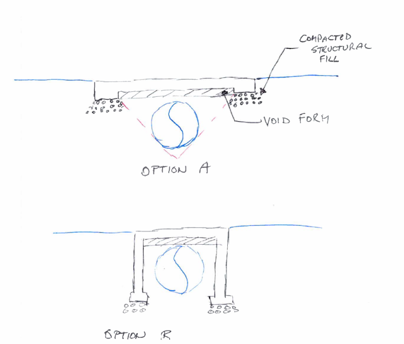
Do you guys know of any reference or guidance to use to design a reinforced concrete cradle or a reinforced concrete slab on top of an RCP? Basically, a road on top of an RCP is going to be lowered to about 6 inches or 1 foot above the RCP and I want to make sure the vehicular loading does not damage the RCP. Thanks
 
Replies continue below

Recommended for you

Can you place void form and span clear across the RCP with your new slab so no load gets applied?
 
That's what I've generally done. Effectively, design the slab as a bridge deck. Carry it long enough so that it bears on compacted material on either side of the pipe and so that a 45 degree line down from the support point doesn't intersect the pipe. Then put void form under everything that's inside of the support points.
 
I am looking into a 72 inch pipe, with possibly 12 inch available from the top of the pipe to the ground surface. Does 12 inches seem appropriate to include the void form (say 3 inches) and slab (say 9 inches)?

Can you please explain, what you mean by support point. Do you basically have the slab extending beyond the pipe, then at the end of the slab you have a thickened concrete section?

 
Oh man, when I saw that title I was trying to figure out how you'd use concrete impregnated fabric to do a crossing. Luckily it wasn't that at all. That detail is basically putting enough concrete in that you create a direct compression path and don't put anything into significant bending. I've done that a bunch, but it might be too tight here to get the required concrete thickness above the pipe. Do it if you can. It's significantly less screwing around with design and field work. You dig a hole and pour in a bunch of concrete.

Option A is a crossing slab, Option B is more of a box culvert.

crossing_t2tpgx.png
 
Variables to get the answer are the RCP pipe wall thickness (Class I to Class V), the type bedding (Type 1 to Type 4), and the vehicular loading requirement (AASHTO HL-93 live load, is common for highways). With the proper combination of values for these variables, and one foot of fill, nothing may be required... just build the road.

For new pipe, the most cost effective option is usually to increase the RCP wall thickness. For an existing pipe, the first step is to determine the RCP wall thickness.

See the RCP Fill Height Tables published by the American Concrete Pipe Association.

[idea]
[r2d2]
 
I would go with option C.
reinforce the slab
extend the footings on either side of the pipe to at least top of pipe or better yet, to the springline. they dont need to go clear down to the bottom


14wxea0.jpg

 
I obtained a little more information on the pipe. The 72-inch RCP was designed for 1200-D, which was designed in the early 80s. Right now the restriction is about 6 to 8 inch height above the RCP. If I place a 1 inch thick Styrofoam or other approved compressible material, that would leave me with a 5 to 7 inch reinforced concrete slab. Do you guys think this might work?

If I assume a Class III (1350-D) pipe was provided, Ordinary Bedding (Class C Bedding) used and use the HS 20-44 for the vehicular loading and impact loading I get about 270-D just using 8 inch of soil with a unit weight of 139 pcf above the pipe. Based on this information the pipe would be alright with just 8 inches of soil above since 270-D is less than the 1200-D provided on the plans. But not sure if providing just 8 inches of soil above the RCP would be appropriate.

Thanks

 
CWEngineer said:
If I place a 1 inch thick Styrofoam or other approved compressible material, that would leave me with a 5 to 7 inch reinforced concrete slab. Do you guys think this might work?

No. The Styrofoam will have to cross the pipe (6'), then extend at least 3' beyond it on both sides. That means the 7" thick reinforced slab will have a clear span of approximately 12' and must carry highway loads... no way. The necessary vertical clearance is just not available to make that solution work.

[idea]
[r2d2]
 
Thank you! For the approximate 12 ft clear span of the reinforced concrete span, approximately how thick should I expect the reinforced concrete slab to be to carry highway loads. Just trying to get an idea with what I have to work with.
 
12 inches, 10 inches if you can use precast concrete. 14 inches if you have vehicle traffic directly applied to the concrete (2 inch wearing surface).

Professional and Structural Engineer (ME, NH, MA)
American Concrete Industries
 
Thanks this information is going to be very helpful.

I was looking at the height of fill (d-load) tables from the american concrete pipe association and noticed that they provide designs for pipes with 1 ft of fill and HL-93 loading. Based on this information if I only place 1 ft of fill above the top of the pipe that would be acceptable and would not require the concrete thicknesses previously suggested. Do you guys still think I need the concrete protection? Why would those tables indicate that 1 ft of fill above the pipe is acceptable for vehicular liading (HL-93)? I am not trying to question your guidance, just really want to understand this topic.

Thanks
 
CWEngineer said:
Do you guys still think I need the concrete protection?

Well, you need a wearing surface. Can't just put traffic on the fill and expect it to last. Loadings, like HL-93, were developed for bridge design where, by definition, there is a wearing surface (the top of the bridge deck, if nothing else). It is reasonable to apply the loadings to roads (with a wearing surface), too.

As I mentioned 8 days ago (2 Aug 16 19:08), with the proper combination of pipe wall class and bedding only one foot of fill and the road (wearing surface) itself may be needed. That recommendation still stands. Since then, you have performed some investigation, made (unsupported, but reasonable) assumptions, and good questions... which have received direct answers (not guidance).

IMHO, the fact that you found a record of the original D-load design suggests that the pipe is class III, or higher.
Try to field verify pipe condition.
Confirm the bedding properties by having some soil testing performed.

If the test/inspection findings and (conservative) pipe-class/bedding/highway-loading calculations checkout... accept the results and proceed. There are occasions for "engineering judgment" and "gut feel", but not if objective measurements can reasonably be performed. With that said, no, I don't believe a concrete bridging slab is needed for 12" of fill and the pipe/bedding conditions described.

To better understand the topic, a good place to start is to buy (and study) the appropriate books from the American Concrete Pipe Association.

[idea]
[r2d2]
 
Did you guys encounter any case where a concrete foundation was directly poured on top of a reinforced concrete pipe (Without any bridge slab) which is not subject to traffic load?
Any simple reference to prove that the pipe will bear the additional stresses from the loads acting on the above mentioned foundation?

Thanks
 
 http://files.engineering.com/getfile.aspx?folder=067b8ce3-1adc-49f2-9366-fed54a0d567b&file=1200_Pipe.JPG
SRE:
You can insulate the outside part of the 'wall' and extend the insulation horizontally. Or, starting from about a foot down, insulate horizontally. Use extruded polystyrene, Type 4.

Dik
 
Status
Not open for further replies.

Part and Inventory Search

Sponsor