Continue to Site

Eng-Tips is the largest engineering community on the Internet

Intelligent Work Forums for Engineering Professionals

  • Congratulations KootK on being selected by the Eng-Tips community for having the most helpful posts in the forums last week. Way to Go!

Reactive power Theory 5

Status
Not open for further replies.

Sofistioelevib

Industrial
Jun 24, 2015
95
Hy Guys,
this is very simple post but it is not so clear with my knowledge.

When i want to change reactive power in a Generator i have to control the excitation current and this is a fact...


Looking at formulas and power triangle i can assume the S=V*I, P=S*cosfi, Q=S*senfi

What exactly happen during change in excitation? Because if excitation currant rise, the output voltage rise so S rise and even P and Q rise itself depending on change ov voltage output.

So how can be possible to change ONLY and ONLY power Q with no changing to the rest?

Thamk you..
 
Replies continue below

Recommended for you

1. You can't change reactive power for a single generator, only the voltage. Reactive power in this case depends on the load.
2. You can't change the voltage for a generator connected to a larger network with other sources. You can change the reactive power import or export though.

Both of the cases above can be applied to the one generator, by changing the excitation.

EDMS Australia
 
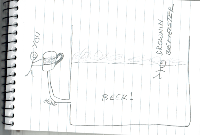
Beer and froth! I wish.

This is where the beer/froth analogy may have some validity.


Beer_and_froth_1_co2lvm.png


You can change the froth level in the stein, which as all electricial guys know, is the Q. But, by doing so, you cannot change anything in the fermenting vessel. And you cannot do much to the V, either.

Der Brauermeister, who so unfortunately fell into the vessel, is fighting for hs life. His death is slow and painful, he has already been out of the vessel four times to take a pee. But his time is over - he is not sure if he can find his way back to the vessel if he tries a fifth time. So he will die. Not so beautifully, but happy.


Gunnar Englund
--------------------------------------
Half full - Half empty? I don't mind. It's what in it that counts.
 
FreddyNurk,
could you please explain deeper both concept? i think it is what really want to know.

Thankyou
 
On a stand-along generator the load dictates what the power factor is. A generator connected to a MUCH, MUCH larger power grid can't change the voltage or frequency of the grid. So, varying the excitation will vary the reactive power imported or exported.
 
Freddy, is right in that a single generator power and var output is tied to the load.

On a power system each generator is tied to each other, and the loads through a network.
Given that, a single generator tied to a network, increase the exciter will export more vars, and cause an increase in the local voltage.
Given that, a single generator tied to a network, increase the power input and will export more watts, and cause an increase in frequency.
That increase in frequency is likely not noticeable, as other generators in the network are likely to back off a little bit, or your generator is too small to notice.

What actually happens is hard to see because of the internal impedances. Increase the power input, and the angular shift of the shaft in relation to the system changes.
Increase the exciter, and the voltage before the impedance increases, so the voltage between the generator and step transformer will also increase.
That increase in voltage will be observed less and less through the system.

Forget the beer, that green beer has a bad taste to it.
 
The load determines the power factor.
The source must supply the reactive power of the load.
Single generator. Changing the excitation changes the voltage.
Grid. Increasing the excitation causes the generator to supply an increasing share of the load reactive power. There will be a corresponding reduction in the power factor of the other generators on the grid. This reduction may be imeasurably small on a large grid.
An increase in power input will tend to rise the frequency, however the swing set will compensate by reducing its power input to hold the frequency at the set point.
Small plants: Several similar sized sets running in parallel but islanded from any major grid. Increasing the excitation will increase the share of the reactive power produced by the set and will also raise the voltage of the plant, but the voltage rise will not be as great as the voltage rise developed by a similar excitation rise if the set is islanded.
Increasing the power input will cause the frequency to rise on plants running in droop mode.
If one set is run as a swing set in isochronous mode this will automatically reduce its power input to compensate for the increased output of the other generator.


Bill
--------------------
"Why not the best?"
Jimmy Carter
 
Sofistioelevib,

The simplified formulas (neglecting armature resistance) that dictate the injection of real and reactive power into the grid by a generator connected to it are:

P = [E[sub]a[/sub]*V[sub]g[/sub]*sin(δ)]/X[sub]d[/sub]

and

Q = [E[sub]a[/sub][sup]2[/sup] - E[sub]a[/sub]*V[sub]g[/sub]*cos(δ)]/X[sub]d[/sub]

where E[sub]a[/sub] is the induced armature (stator) voltage produced by the rotor field, V[sub]g[/sub] is the grid voltage, X[sub]d[/sub] is the generator direct-axis inductive reactance, and δ is the power angle - the angle of E[sub]a[/sub] referenced from V[sub]g[/sub].

If you do a sensitivity analysis using partial derivatives of both P and Q with respect to both δ and E[sub]a[/sub] - the two variables the operator can control (δ is controlled by the governor no-load setpoint and E[sub]a[/sub] is controlled by the exciter no-load setpoint) - and substitute typical values for all terms, you'll see that P is much more sensitive to δ than E[sub]a[/sub], and Q is much more sensitive to E[sub]a[/sub] than to δ. Therefore, δ is used to control P injection and E[sub]a[/sub] is used to control Q injection/absorption. It isn't that changing δ by a given percent doesn't change Q, it just changes it very little compared to the same percent change in E[sub]a[/sub]. The same can be said for E[sub]a[/sub] and P.

Does that help you understand why reactive power is controlled by the exciter?

xnuke
"Live and act within the limit of your knowledge and keep expanding it to the limit of your life." Ayn Rand, Atlas Shrugged.
Please see FAQ731-376 for tips on how to make the best use of Eng-Tips.
 
Sofistioelevib,
The subtlety is that its the same generator in both cases, the difference is not in a particular generator, but what its connected to.

Changing the excitation, as you noted, changes the voltage at the set. The effect of changing the voltage at the set depends on what is connected to it. As others have also noted, changing the reactive power is not an isolated operation, if you reduce the reactive output on your set, somewhere else in the network will increase its reactive power to provide the required amount to the load.

EDMS Australia
 
I was on a vessel (A fish cleaning and freezing plant built on a 200 foot scow.) with diesel power during commissioning. We were trying different combinations of machines and generators to get a feel for what could be done so we would lessen the chance of an embarrassing impromptu education when we were on station on the fishing grounds.
One day we were running two generators in parallel with a load of mostly motors at about 80% PF.
We tried to bring a generator up to 100% PF.
We adjusted the excitation but that also changed the frequency slightly.
We adjusted the frequency but that changed the PF again.
Every change we made had an unexpected result as well as the desired result.
After much tweaking we got one set up to 100% PF.
Then we stepped back and looked at the instruments of the second set.
kW: Very low.
PF: Very low.
Amps: Near full load Amps. (Connected load, not rated load.)

The first set.
kW: Nearly the full load.
PF: 100%
Amps: About 60% of full load Amps. Actually higher than the original Amps. (Connected load, not rated load.)
Note originally the sets were sharing the reactive current.
When the set was supplying the full amount of reactive current, the reactive component doubled.
kW: Near full load. This set was supplying almost all of the real power.
This was an excellent illustration of the interconnectedness of all things.
As confusing as it seemed, all of the interactions were in accordance with the previous posts.

The reason that two sets were running when only one set could supply the load was actually two issues.
1: The blast freezers shut down banks of fans to defrost sections of the freezers.
2: The initial protection settings were too tight and the starting inrush of a bank of motors starting would trip a single set off-line and leave the vessel in darkness. When this was rectified we could run on one set.
Then another bank of freezers came online and we were back to two sets. With the original settings we would have to have used three sets, so we were ahead.


Bill
--------------------
"Why not the best?"
Jimmy Carter
 
Easiest way I've explained it is that for motors and generators, reactive power is the magnetizing power needed to produce the horsepower. That reactive power has to come from somewhere.

On synchronous machines you get the option of producing the vars from excitation or taking them from the system at large. If you don't excite enough to produce the needed VAR, then you run a negative power factor because you're importing VAR from elsewhere in the system. If you over excite, you 'create' too much VAR and you run a positive power factor because you're sending VAR out into the system.

On induction machines, you have no way of 'producing' the magnetizing energy, so you import VAR from the system.

I've had the opportunity to teach this lesson a few times while standing alongside the controls for both synchronous motors and synchronous generators.

If this explanation doesn't help, I apologize in advance.

OFG

old field guy
 
Excellent almost non-mathematical way to explain it! I'll remember that one / keep it in my back pocket; thank you.
Your chosen moniker/handle would actually have been quite fitting for me, too, although if I had ever put OFG at the end my colleagues would have riposted, "Oh! So the 'F' in your initials stands for 'Field'..." [noevil]

CR

"As iron sharpens iron, so one person sharpens another." [Proverbs 27:17, NIV]
 
The term 'Reactive Power' is an oxymoron.

The point is that there is no power.
 
Only if you define 'power' as exclusively 'real' and no other way...I don't see an issue with saying real power is the product of current in exact phase with voltage and reactive power is the the product of current in quadrature with voltage.

CR

"As iron sharpens iron, so one person sharpens another." [Proverbs 27:17, NIV]
 
Hoxton:

If you examine at a low level what happens with the reactive power, you see that it is transferred from the source twice per AC cycle, increasing the inductive* energy of the system, but then returned to the source twice per AC cycle as well. But the source must be able to provide this physical power in this manner, or the system does not work.

To use a financial analogy, reactive power is like a short-term loan rather than a one-way payment.

*In the general case, the reactive power could also be stored as capacitive energy.
 
To take the analogy one step further:
You have to pay interest on the loan.
That's the I[sup]2[/sup]R losses of the reactive current.

Bill
--------------------
"Why not the best?"
Jimmy Carter
 
Curt & Bill
Almost as good as the beer/froth analogy. Better, actually.

Gunnar Englund
--------------------------------------
Half full - Half empty? I don't mind. It's what in it that counts.
 
It always surprises me that this comes up over and over and over and over. I have worked with very experienced engineers asked what VARS are and have gotten very odd responses. Operators ironically seem to have better understanding of what VARS do. Switch in capacitor banks and it improves PF of powerflows and raises the voltage. If the voltage is too high, switch out the capacitor bank.

Here is how it makes sense to me:

You can't transmit real power without current.

Currents create magnetic fields around the conductors and wires.

VARS is power that is flowing back and forth as the magnetic fields expand and collapse.

VARS does no real work.

You would like to only be transmitting energy that is doing real work over the grid.

VARS uses up capacity, creates additional losses, and due to additional current creates larger voltage drops.

If you can deliver the VARS near were they are needed you can transmit more power that is doing just real work over the grid without the losses, loss in capacity, and voltage drops.


------------------------------------------------------------------------------------------
If you can't explain it to a six year old, you don't understand it yourself.
 
Status
Not open for further replies.

Part and Inventory Search

Sponsor