Hello,
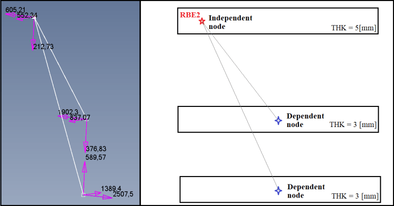
I am using RBE2 elements to represent bolts that link three plates together.
The dependent node is in the top plate (where the load comes from) and the other two dependent nodes is one in each one of the bottom plates.
I leave an image below so it is easier to understand.
I have several questions :
[ol 1]
[li]Is there a way to read the total load on the bolt ? I mean, in the image above you can see the results. I've checked that the components add to zero in all directions, but I would like to export only the total values of load for the bolt (which in this case would be the values for the bottom plate). Because otherwise I will have a lot of repeated or useless data of forces for a single bolt. What I am trying to say I think is if there is a way to export the loads on the element rather than in the nodes. Maybe the question is already clear and I am trying to overexplain it.[/li]
[li]What do you think about this strategy to link with a RBE2 three plates ? In your experience is there a more appropriate solution ? [/li]
[li]The mesh in the two bottom plates is coincident, but not for the top plate. Do you think that having a RBE2 elements that it is not straight might be a problem ? My guess is that it is not given that the RBE2 is infinitely rigid then the loads will transfer exactly the same no matter the orientation of the element.[/li]
[li]Is there in FEMAP an easy way to export results from MPC forces like in the image? [/li]
[/ol]
Thank you very much in advance for your time !
Cordially,
EC
")