Eng-Tips is the largest engineering community on the Internet

Intelligent Work Forums for Engineering Professionals

Reading Wind Speed for Heat Transfer Wind Tunnel

Status
Not open for further replies.

jnelson33

Mechanical
Mar 7, 2018
51
0
0
US
I am in a predicament: Would you use an anemometer or pitot tube with a pressure transducer to collect wind speed measurements in a low speed wind tunnel?

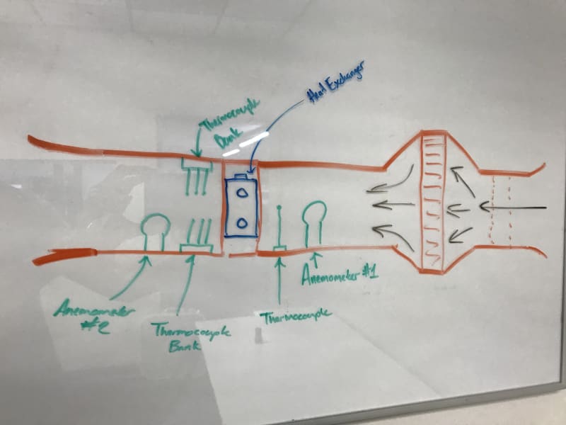
Here's the catch: This is a heat transfer wind tunnel, specifically for heat exchanger rating, therefore the air passes through the entire core, and not around it like an aerodynamic study.

I only bring that up due to the pressure wall that will exist at the face of the heat exchanger's core, and for the fact that the air being metered fore and aft will be different temperatures (densities).

Neither an anemometer nor pitot tube is fully immune to that change in density, but my thinking is that the pressure transducer is going to win here, even though I know that density isn't that big of a change.

I really just want to bounce the conversation around and make sure I'm thinking about this correctly because that pressure wall will affect how an anemometer spins if there is turbulence or a low pressure zone which is aft of it.

That being said, I understand that placement is everything here, as either option will be spaced away from the pressure wall zone by enough distance, but as close to the heat exchanger core as possible to keep the equation for studying these valid too.

I believe that the anemometer will be more useful with what we're doing, and it'll save me from having to do my initial calibration for the pitot tube to read accurate wind speed in the test section. Is this agreeable?
 
Replies continue below

Recommended for you

pitot tube and a temperature sensor (for density).

I suspect that you'll need multiple measuring stations … two either side of the heat exchanger to capture the effect of the heat exchanger, and two further afield (upstream and down) to capture general flow properties.

another day in paradise, or is paradise one day closer ?
 
"...and for the fact that the air being metered fore and aft will be different temperatures..."

Would it help if you were to have the heat exchanger inactive (neither hot nor cold) for some initial calibration testing?

I'm assuming that the different temperatures mentioned above are from the heat exchanger, not as a result of the pressure drop across it.

 
A pitot tube is sufficient and doesn't really require calibration; normally you'd hook it and a static port in the side of the tunnel to a slant tube manometer with fluid of known density to determine the dynamic pressure. Companies that supply manometers also supply calibrated fluids.

Of course a number of thermometers would be useful to see the up-close temp distribution, and one downstream to catch mixing, would give the overall temperature change.

A u-tube/slant manometer could be used to measure the static delta-P; I have no idea what use the downstream/exhaust speed would be. The density change is from the change in temperature and if you know the mass flowing in, you know the mass flowing out.
 
Since Pitot tube relies on the the difference between total and static pressure, I guess the physical quantity at stake is the dynamic pressure which itself would allow obtaining the velocity (knowing the density). What I mean to say is that at low velocity, your instrumentation and data acquisition system might need to have sufficient sensitivity and resolution to capture probably small variations of velocity and dynamic pressures with descent systematic uncertainty. My take on it to trigger some discussion. I only did aerodynamic study and might be off the mark.
 
rb1957 I suppose that is a decent way to do it, although the initial X-Y point traversing is really what I'd like to avoid. I will for sure need two stations for this, seems like I forgot to make that clearer in my initial post.

VEBill I would perform those experiments on the heat exchangers first and then see how significantly the results vary with heat being removed from it too. [thumbsup] Do you have an opinion on which test instrumentation you'd prefer as well?

3DDave Ya they're simple enough in the end, although very laborious to set up if you actually want to establish the correct wind profile in the test section. I'm trying to reduce X and Y point traversing at all costs. If I did do this method, I'd have them connected to a pressure transducer instead as this is a computer read test system, thus I'd have it transmitting 4-20 mA (or similar).

rotw Makes sense, we are going to be testing with a minimum wind speed of 30 MPH, but likely in the ranges of 50-60 MPH instead.

IRstuff I'll have to do some more research on those and see if the pricing is even realistic for us here.
 
I also forgot to mention that this is a computer instrument testing system, therefore all options have to be able to transmit analog/digital signals.
 
MintJulep I've seen that type of thing before but forgot to file it in my memory for later research. I've only seen them on extremely large wind tunnels or like outside of coastal weather station maybe; can't recall for sure now?

If I'm thinking correctly, these things typically sit in the test section, fore the heat exchanger? And then in my case, I can just add another aft of the heat exchanger for determining core pressure drop, and of course my heat calcs. I am also thinking that they have to be in the center of the chamber, or is that a nozzle's strong point?

The interweb is showing very limited, general wind tunnel design when I search "AMCA/ANSI standard air flow nozzle wind tunnel" and that website is lacking implementation info as well.
 
I understand needing just one for the thermal rating aspect, but per air's pressure drop through the core, I was thinking that is why I would need another. I suppose if I am metering air with one nozzle to understand the flow right before the H.E. then I could just use a pressure transducer to rate the core pressure drop with respect to the air moving across it.

I will contact that company regardless because I need to understand more about these first.
 
Flow nozzles didn't end up being efficacious.

Due to the test chamber size versus the current fan we're using, the Helander Metal rep said I'd be better off with anemometers instead. Since that means more money for my boss to outlay, we're looking at third party testing finally, even though we have a half finished test system now [upsidedown].

Here's the pic I should've posted the first time I made this thread btw.
IMG_7847_jsijsa.jpg
 
I wonder if other flow visualisations would work ? like schlieren photography, etc ?

Have you done CFD on this ?

another day in paradise, or is paradise one day closer ?
 
I wish we had Solidworks so I could use their paltry CFD; Inventor Professional still doesn't have something basic. My boss likely won't pay to send this off either..

We'll see if NTS can help us out, otherwise we're going to try and see what else is out there, or I'll finally get to finish this system properly.
 
we've used Inventor CFD … but only for studies, not for anything "proper".

another day in paradise, or is paradise one day closer ?
 
That's going to have a nasty performance where there is a sudden change in section. You won't need the bank of downstream thermocouples as the air will be massively turbulent in that area.
 
Autodesk makes their own CFD software of which you can import an Inventor model, correct, but our reseller has not included that in the collection that we use. Solidworks is all internal to the actual software; but way less detailed than something like STAR / ANSYS.

Kays & London actually pioneered the whole heat exchanger testing industry using a more advanced version of my crude sketch; it's all outlined in Compact Heat Exchangers. I've worked with Temprel to create a robust enough exposed thermocouple for our needs; I can easily order more. I understand that the air will be turbulent, that's why Kays & London used so many to average their values to a mean value for their equations. That's why I would do the same since the photographic methods are going to be out of our price point.

I think I've got it from here, dang first ideas are usually the right ones!
 
The turbulence does the averaging for you. Thermocouples are too slow to pick up the turbulence.

What I cannot figure out is this - you know the delta-T of the liquid and the flow rate, so you know how much heat is being transferred. What difference does the downstream temperature make? You need to know the delta-T across the fluid interface and the delta-T between the inlet liquid and the inlet air. After that you can calculate the average temp rise of the air for any number of combinations of air pressure and humidity.
 
Status
Not open for further replies.
Back
Top