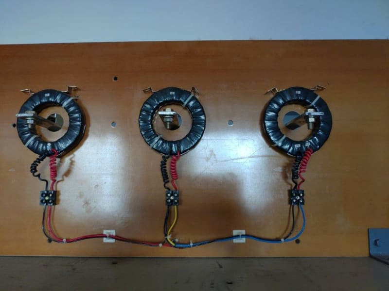
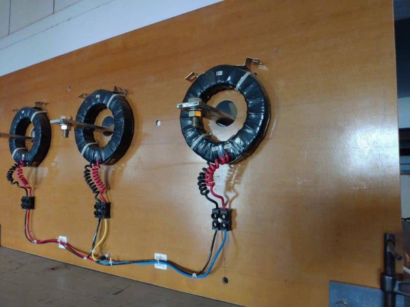
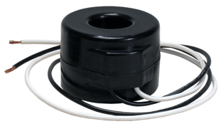
What is the recommended air clearance between a donut type CT (rated for 690 V like shown below) and a 11 KV bare busbar?
Is there any standard to refer to? Thanks.
Muthu
Is there any standard to refer to? Thanks.
Muthu
")