Continue to Site

Eng-Tips is the largest engineering community on the Internet

Intelligent Work Forums for Engineering Professionals

  • Congratulations IDS on being selected by the Eng-Tips community for having the most helpful posts in the forums last week. Way to Go!

Referencing centre lines

Status
Not open for further replies.

R1chJC

Marine/Ocean
Apr 15, 2015
51
Hi All,

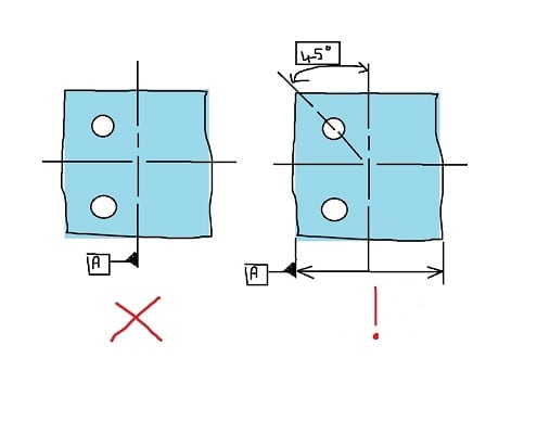
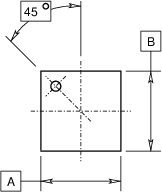
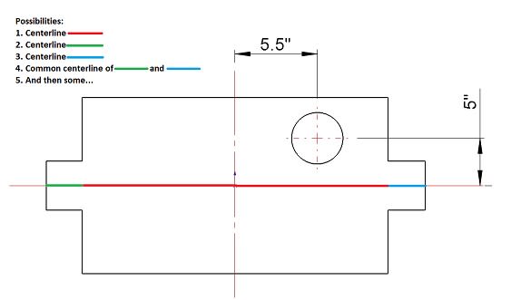
So referencing centre lines or part axis as Datum Features is not legal, no problem, I understand why.

However, I see drawings that reference such centre lines or axis for linear and angular dimensions all the time (at least where I work). Can someone explain the difference?

See attached.

To my mind these are equally ambiguous.
 
 https://files.engineering.com/getfile.aspx?folder=e5ac5e61-83d6-4568-a3de-e9db1d3d967e&file=Axis_reference.jpg
Replies continue below

Recommended for you

Assuming that GD&T is being imposed there, the difference is that those dimensions (linear or angular) are taken from the datum. By definition, the datum is the theoretically exact center plane or axis (if we're talking about a feature of size). And by definition, the datum center plane/axis is derived from the datum feature, which is precisely what the triangle symbol is identifying.

John-Paul Belanger
Certified Sr. GD&T Professional
Geometric Learning Systems
 

Hi Belanger,

Not sure I follow.

If there was no GD&T called out for the angled hole at 45 degrees, from what FOS is the centre line established?
 
R1chJC,

You are comparing apples to oranges.
If there is no GD&T called out, then there is no datum feature to consider and nowhere to attach the symbol. Nothing to talk about.

But if you are using GD&T, you specify exactly center of what is the datum, so you don't apply datum feature symbol to the axis, but to the feature itself according to the standard.

Axis_reference_k1ktje.jpg


"For every expert there is an equal and opposite expert"
Arthur C. Clarke Profiles of the future
 
R1chJC,

Here is my version of what you are doing.

CentreLines_itrsay.png


What I show is legal, but it sucks. Datums[ ]A and[ ]B are attached to features of size I did not bother to dimension, although that would be mandatory on a serious drawing. The centre-lines and the centre of the part are defined by the datum features. A radius dimension from the centre is horrible drafting. Almost certainly, there is a better way.

When you prepare drawings, always ask yourself how it will be inspected.

--
JHG
 
Hi All,

Ok gotcha both.

But what if the hole has no GD&T applied?
 
If no GD&T is applied, then there's no point in labeling the datum features! What you are talking about is the coordinate tolerancing method, and one of its main shortcomings is that the datums are implied, not explicit.
(Exception: an elaborate note might be used to communicate a GD&T-like tolerance for the hole, and that might need datums ID'd, but that's a weird offshoot of this discussion.)

John-Paul Belanger
Certified Sr. GD&T Professional
Geometric Learning Systems
 
Hi Belanger,

Yes so i think we are in agreement.

What prompted my original question was a part similar to the attached. I see drawings tolernaced like this all the time and our checkers don't usually pick up on it.

However they are quick to point out if an ambiguous datum feature has been applied such as an axis. I suppose it depends on the functional intent of the features being toleranced.
 
 https://files.engineering.com/getfile.aspx?folder=2eac2e81-a88f-4b83-bdc0-7dce5ee6f013&file=Centre_line.jpg
R1chJC,
You still work hard to create a confusion. Please explain.
In real life, on the drawing you have shown, is the datum feature symbol applied to ANYTHING?
Is feature control frame applied to the hole, or ANYTHING?
Because if your "checkers" insist on "correct" application of datum feature symbol, but fail to relate anything on the drawing to datums, your set-up is completely meaningless, and, once again, there is nothing to talk about, it's just garbage.

"For every expert there is an equal and opposite expert"
Arthur C. Clarke Profiles of the future

 
Hi CheckerHater,

Thanks for replying,

There was not meant to be any datum features or FCF's on my previous drawing example.

I was trying to illustrate a drawing whereby there was no GD&T applied but instead had simple X/Y coordinate dimensions applied to identify the holes centre point. I omitted the hole size limits.

I see this style of tolerating often, particularly on drawings where people aren't familiar with GD&T.


There is nothing wrong about dimensioning from center lines.

Only if you decide to use GD&T symbology, it is your responsibility to correctly specify, where the centerline is derived (see picture):

Centre_line_cjhxbh.jpg


"For every expert there is an equal and opposite expert"
Arthur C. Clarke Profiles of the future
 
R1chJC,

Your drawing is a perfect example of why we should use GD&T positional tolerances. I can see four ways to define the horizontal centre-line, and four ways to define the vertical one. Maybe we know where the hole is, and the dimensions are showing us where the centre-lines are! Datums specify what features control those centre-lines. This drawing is uninspectable.

--
JHG
 
Status
Not open for further replies.

Part and Inventory Search

Sponsor