Eng-Tips is the largest engineering community on the Internet

Intelligent Work Forums for Engineering Professionals

Refrigerant flash in P-H diagram 1

Status
Not open for further replies.

Cheetos

Mechanical
Jul 27, 2007
56
0
0
US
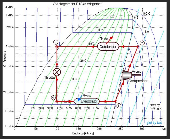
I'm going over the P-h diagram for R-134a. I was wondering how I can explain "flash" in P-h diagram. The refrigerant starts in the liquid state, but, through pipe resistance, head lost...etc, the refrigerant will flash off. I just don't know how to explain that phenomenon in P-h diagram.
 
Replies continue below

Recommended for you

First locate the initial P/T on the P-h diagram. Note the enthalpy at this point. Then move along the constant enthalpy line to the lower pressure point. This process is called an isenthalpic flash.
 
Thanks georgeverhese! If I do that, I'm assuming once I enter into the vapor dome, that's when flash happens. Since I'm always going downward toward the lower pressure point, does that mean it will always be in 2 phase region? There won't be a case where the liquid completely flashes off and becomes 100% vapor?
 
At the lower system pressure point george mentioned, use the "phase rule".

Good luck,
Latexman

To a ChE, the glass is always full - 1/2 air and 1/2 water
 
"... I just don't know how to explain that phenomenon in P-h diagram." If you have isenthalpic flash then you have to know the end condition that is the pressure and obviously the constant enthalpy value in order to determine if the vapor is in a saturated or superheated state. Now look at my attachment of a generalized Mollier diagram for any refrigerant. At point 1 is the initial condition of the liquid phase as you stated. At point 2 at constant enthalpy is the flash condition which basically is in the saturated region ie two states liquid and vapor. How much liquid and vapor that you have will be determined by the quality value at point 2. You can figure the quality value at point 2 by fractioning the enthalpy values at the saturated liquid and vapor lines to that of the value at point 2 along that constant pressure line p3 within the saturated region.
 
 https://files.engineering.com/getfile.aspx?folder=aa8144c3-0b17-4d13-afc6-9b1dba0b3a5d&file=Reply_to_Thread_391-452395.jpg
Thanks for the response chicopee. Based on your explanation, I was curious about whether it is possible to completely flash off the liquid and turn it into 100% vapor due to pressure loss. Please correct me if I misunderstood. If I lower the pressure with constant enthalpy, I would go into the vapor dome and will always have a liquid/vapor mixture, no matter how much I flash off due to pressure loss.
 
Don't call it a vapor dome as it is known as the saturated region. To your second question ,no,if it is an isenthalpic process. Yes if you could heat up the refrigerant after the isenthalpic process which by the way would be similar to the operation of a vapor compressor cycle found in refrigeration system.
 
Capture_ay8wh4.jpg


Good luck,
Latexman

To a ChE, the glass is always full - 1/2 air and 1/2 water
 
cool. Thanks guys for your help. I think I understood it now. If it is just pressure loss due to transport or throttle, it'll go into a 2 phase region. The mixture will not turn into a complete vapor unless you have additional heat input.
 
To know the mass fraction of liquid to vapor in the 2phase region, use the "inverse lever rule". If the horizontal distance from this point to the !00% sat liquid point (at this same pressure) is x, and the distance to the 100% sat vapor point is y, then the mass fraction of liquid at this 2 phase point is

XmL = y/(x+y)

You will probably find this rule in your thermodynamics textbook or class notes. So the closer the point is to all vapor, then the greater the mass fraction of vapor.
 
Frictional loss in piping is often approximated as isenthalpic, and this applies only when pressure drop is low. Strictly speaking, there is a small enthalpy drop commensurate with the increase in stream kinetic energy in this adiabatic process. If you must account for this, convert the pressure drop into enthalpy loss and find the new enthalpy point at the lower pressure in the 2phase region.
 
As you stated in your last reply following Latexman's presentation of the R134a refrigerant Mollier diagram is that heat input is needed between point 4 and 1,which is true, but not knowing the intent of your OP I should remark as a cautionary measure that point 1 should be about 5 degrees into the superheated region because vapor compressors do not like any amount of liquid.
 
Status
Not open for further replies.
Back
Top