Continue to Site

Eng-Tips is the largest engineering community on the Internet

Intelligent Work Forums for Engineering Professionals

  • Congratulations KootK on being selected by the Eng-Tips community for having the most helpful posts in the forums last week. Way to Go!

Regarding Seismic Analysis of Space frame and architectural feature 1

Status
Not open for further replies.

Arbu

Structural
Mar 25, 2018
69
Dear All,

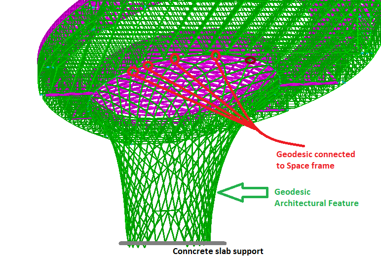
I am designing a space frame which is supported on steel columns. there is a central architectural feature as well. when I am modelling all structure in one model and running seismic analysis, then central architectural feature is taking to much load and members are failing (due to moment and compression) . The central architectural feature is made up of 114x6 mm pipes welded. Please suggest some method of modelling in STAAD such that only columns will carry lateral loads.
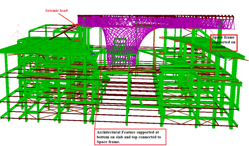

seismic_ikrlox.png
 
Replies continue below

Recommended for you

Enggsigma
Can I rephrase your question a bit?

Please suggest some method of designing and detailing my structure such that when I correctly model it in STAAD that only columns will carry lateral loads.

If you’ve Correctly modeled your structure the results of a computer analysis will reflect a true behavior.

Seems like you are trying to adjust your model to get the results you want instead of starting with altering your design.

Check out Eng-Tips Forum's Policies here:
faq731-376
 
Dear JAE,

you are correct.
but our scope of work is Space frame and architectural feature only, the main column and beam is done by other company. And they are not allowing us to make changes in there model.
 
Usually seismic forces are not a problem for Space Frame structure since SF is not very heavy
That funnel...is it Space frame ore single layer structure ?

You probably have to make support to main steel sub structure (green structure) in a way so it is vertical support only
this way your structure is more independent from horizontal movement of main structure
The funnel should be stiff and strong enough to take down any horizontal load ( wind) on the SF
 
We call that architectural feature as Geodesic. Geodesic is a single layer structure and it s inside of building.
 
You may want to try to seismically isolate this thing from the supporting structure. Perhaps have it bear on teflon slide plates?
 
I suspect you are seeing some effect of differential movement across the supports due to trying to constrain the building movements. As WARoss noted, try to release the constraints such that you are only transferring the loads from the feature structure to the base building, and not transferring building forces through the feature structure.

Check the lateral deflections at the supports, if you are seeing a difference on each side, then your structure is being compressed or stretched horizontally to accommodate this. If it's appropriately released and supported then these compatibility forces should be minimised.
 
I'm assuming that the problem is that your big circular cross section is taking all the shear?

Slide plates and isolation at support points is fiddly and hard. It's better if you can just break the load path somewhere.

Can you hang the whole architectural feature so that it doesn't anchor at the bottom? If not, can you structurally break it part way up the height so you actually have two items, one of which is hanging and the other which is resting on the bottom then visually tie them together somehow without adding strength?

 
Alternately, consider if your architectural feature is actually as stiff in shear as you're modelling it. Can the walls buckle and release the load? Will it yield and deform? This is likely only a good failure mechanism to let happen if it's some sort of thin wall shell that also has some ductility or you can otherwise determine that it won't break and fall on people.

This type of behavior wouldn't be captured in an elastic analysis and you'd just get a really stiff overstressed section because of the closed shape.
 
Too add to my previous response, I didn't pick up that it was supported laterally at the top and bottom, I thought it was entirely suspended from above via the truss like structure shown.

If it is fixed laterally between levels you need to try things like allowing the base to slide horizontally on the floor at the lower level, combined with sufficient restraint at the top to maintain stability but minimise any forces being locked in from the primary structure. You need to allow for the building drift to happen without constraining your feature to the same drifts.

I'm assuming you have it attached to the primary structure at the top level and the bottom level which basically means without some isolation that the feature is stiffer laterally than the primary structure, so its trying/acting to brace your entire structure.
 
Dear All,

thank you for the reply I am going with base isolation.

Regards,
enggsigma
 
Dear All,

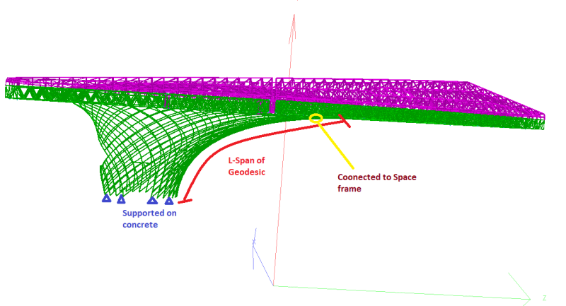
For the same Geodesic Structure above (Architectural feature). Consultant has given me comment that there is no intermediate supports for members of geodesic therefore need to provide Lz (length of major buckling) for the pipes. The Geodesic structure is supported at bottom on concrete and top it is hanging from Space frame as shown in below fig. My doubts are,

1. Is it really mandatory to assign Lz (Length of major buckling)in STAAD pro software. Members acting here are like beams, then also its mandatory to check for buckling.
2. If its mandatory to apply length for buckling then what length Iwill apply, If I am taking the same length all pipes are failing in Slenderness as per LRFD ASCE.
3. Is there is any method to get the effective length for buckling of such a grid structure, for sure buckling will be not similar to full length individual members.
4. Or can I make model of this geodesic and run buckling analysis to get buckling shape. And after getting buckling shape can I use the First mode shape for application of Lz.


22_ropybx.png


11_f2wn2f.png


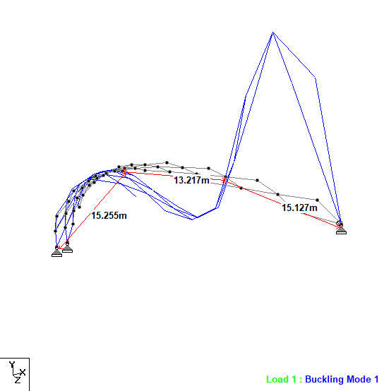
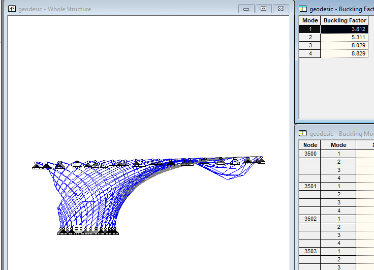
From the buckling analysis I got first mode as below, Please check and confirm that can I follow these lengths as Lz for main members.

first_mode_vnzkd1.png
 
You need to run a buckling analysis, but instead of estimating the length from the mode shape. Back calculate the K factor from the standard euler eqn using the critical elastic buckling load given by the analysis. I.e. rearrange P_cr = pi^2*EI/(KL^2) to determine K. From this point on use this length and design the critical member like any other member.

Importantly you need to be sure what the buckling analysis is giving you, you will likely need to sub divide the members to get an accurate representation of the buckling behaviour (don't ignore this aspect, you can check by creating a model with a single member and keep subdiving it until you get a P_cr result that is consistent with the theoretical Euler buckling P_cr).

Sometimes the program you use might output the buckling length directly.

If you can verify the model/geometry/buckling analysis results in a second program.

Lastly make sure you account for realistic boundary conditions as the buckling loads can be quite sensitive to this aspect (if something is 'fixed' then ensure you represent the rotational stiffness appropriately).
 
Dear Agent666,


Thank you for your information, its very helpful.
I am trying follow the steps what u explained above. If u know any programme or software which will give directly buckling length or Euler's buckling load then please let me know. I am using STAAD and its giving Shape of structure.I will check once again in STAAD if possible to get buckling load.
Apart from this I have a doubt that how I will models these members in that model/programme.

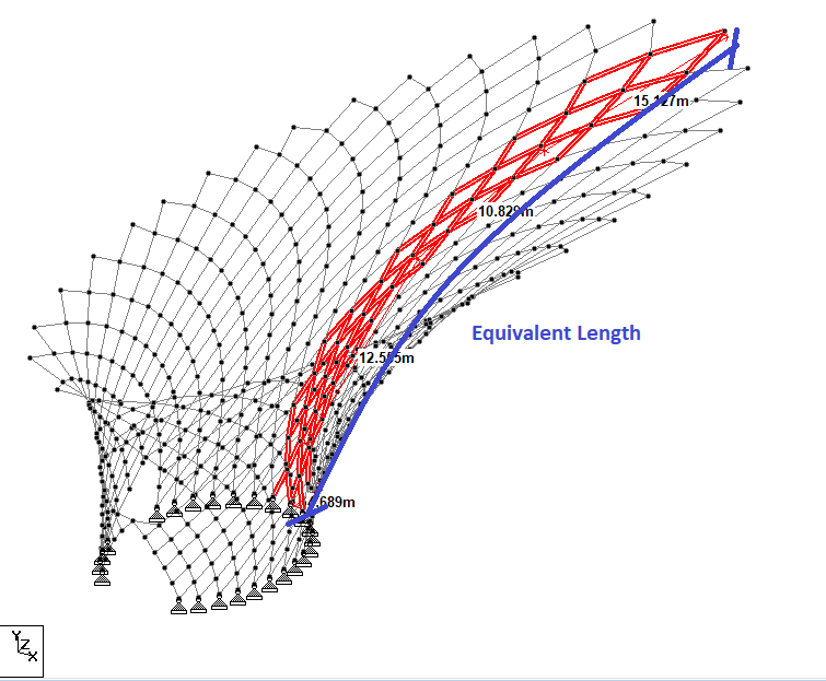
1. Can I model a single pipe with exact length following its profile, as shown below.
one_memeber_oxivwb.png


2. Or I can model a portion taking equivalent Moment of inertia and length as shown in figure below.

equivalent_xtdrxz.png


this architectural feature is supported at bottom on concrete with anchor bolt and top it is hanging from Space frame that's why I am considered both the ends top and bottom as hinged support.
 
With that shape, your buckling action is going to be unusually similar to the buckling of a shell surface, but with individual members instead of plates. The individual stiffnesses will all interrelate. In my mind, the best way to get a reasonable estimate of the buckling behaviour in a computerized analysis is to include the whole system. If you take only part you'll either massively underestimate the strength by completely neglecting the stabilizing effects of the ring action or you'll massively overestimate the strength by replacing those member connections with stiff supports.

If you need to simplify it down to get comprehensible results from the software, you could presumably calculate a spring stiffness representing the rest of the structure at every single nodal connection, for ever degree of freedom. That sounds like a pain though.

Consider the buckling capacity of a pipe. Now consider the buckling capacity of a arc of the pipe wall cut down the length. That's the comparison between looking at the whole system and cutting a piece out. The ring compression/tension has a stabilizing effect.
 
As TLHS noted, you need to run a buckling analysis on the entire assembly rather than trying to isolate some section of it. Most credible software has an option to do a buckling analysis, it might be call elastic critical load analysis, or some other similar name.

Link, this seems to suggest that staad has this analysis option.

What it usually outputs is a load factor by which you can increase the applied loads by to reach the critical buckling load of the most critical member in the system.

Just to clarify, in my last post the euler critical buckling load should be P_cr = pi^2*EI/(KL)^2

To learn a bit more about the fundamentals of buckling behaviour and analysis I would recommend looking at/working your way through the stability fun modules of mastan2 (a free program). Link
 
Dear Agent666 and TLHS,

thanks for sharing the information, its very useful.

I was trying to get the effective length of Geodesic shape as a full unit. I followed the following steps.

1. Modelled geodesic separate and run buckling analysis in STAAD.
2. Got buckling factors from output (First mode 3.812).
3. then member axial forces multiplied it by first buckling factor from STAAD to get the buckling load.
4. Put this buckling load (Assumed buckling load for every member) in Euler's formula to get the KL .
5. But following issues I found in the process.

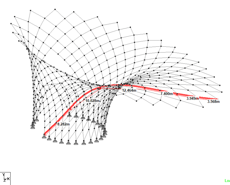
first_mode_xfdxlx.png


- The factor STAAD giving is for local point some where in model, but the joint or member cannot be located. By considering same factor for all members might be buckling capacity of some members will be underestimated.
- Apart from this some members are in tension with very small axial force. These members with small axial forces are giving very large length like KL = 80 to 100m. I think this process is giving allowable length for the assumed buckling load.
- If the member having maximum axial force is considered as governing then the effective length (kL) will be 5.66 m only.
Calculation: ( Moment of Inertia = 3e6 mm^4, E = 2e5 Mpa)
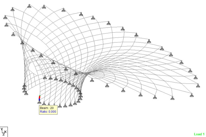
maximum axial force in beam (beam NO-20) =48.145 kN
factored buckling load for member = 3.812 x 48.415 = 184.55 kN
Euler's formula, P = Pi^2 EI/(kL)^2
KL = 5.66 m

But this member (No 20) is located at the base of Geodesic (see attached image), So if this kL will considered for all members then it will overestimate the strength of members.

20_z7utmv.png


Please guide.
 
I don't really think you can backward calaculate the effective lengths of members this way for this type of structure. It's not really a useful piece of information. Your axial loads won't be constant along a length between nodes, I suspect and your buckling shape incorporates a large region. I get it for something like a straightforward frame, but this is very much a composite buckling shape incorporating all the members. I'd be open to correction on this, though.

Have you split your members into multiple lengths? I think the advanced solver does it better, but at least the basic analysis engine uses an iterative buckling analysis that doesn't work unless you have intermediate nodes that can displace. About ten segments is the sweet spot, I think, but you should really just keep splitting members further until your solution stops changing with greater divisions.

You need to be way more certain that you're comfortable with this type of analysis than you seem to be. Go spend a day reading absolutely everything you can find STAAD's buckling analysis basically blindly analyzes your load case completely. It can be pretty tricky. You have to have a general understanding of what might cause buckling. Load cases with destabilizing forces at the same time as your primary load are likely good ideas, as are loading cases with partial live or environmental loads that could create instability. I'd also be running general sensitivity cases to figure out what types of loads are the worst and in what numbers. Then I'd be looking at those results and making sure they match my mental model of how the structure will act.

The GUI also just reports the buckling factor for the last load case analyzed (or at least used to). It calculates factors from other load cases, but you need to read them out of the output file.


I have done lots of stuctures like that
You need to do 2 things for stability check

1) global stability
Use your model
impose imperfect structure ( different ways to do that )
do geometric nonlinear calculation (e.g. second order theory)
check if the system is stabel and check stress for the results

2 ) local buckling of the members
do for each member local buckling check 'by hand'
by hand means maybe excel or similar if you software cannot hande this automatically

buckling lenght = lengh of member


Arbu

What you need to appreciate is that the buckling analysis is giving you the theoretical buckling load for the first member (or group of members) that buckles. You cannot infer anything beyond this for the other members that have not buckled which it sounds like you are doing. Following the procedures in your code for converting this theoretical buckling load to the failure load of a real column with initial imperfections is critical to getting the real capacity (which is obviously less than the theoretical capacity).

If you find that the bucking load doesn't work, increase member sizes to address the buckling mode, and rinse and repeat.

I'll explain the process my own local code uses for determination of member capacity based on the use of a 'rational buckling analysis', I'm sure AISC has something similar if that is what you are working to.

1. use a rational buckling analysis to determine the theoretical critical buckling load (N_om), identify the member or group of members buckling through looking at the mode shapes (do a reality check, is it what is expected).

2. work out a modified slenderness parameter (lamda_n = 90 * sqrt(N_s/N_om)), where Ns = A_g * f_y (i.e. the full section capacity/squash load)

3. use this modified slenderness parameter to work out the capacity of the member in the normal manner, basically in my case working out from the modified slenderness parameter a alpha_c reduction factor to reduce N_s to the true design capacity accounting for buckling (not covered here in detail as its quite a bit different to AISC provisions). This process applies the standard column buckling curve to your unique situation when due to complex geometry you cannot manually assign one of the tabulated theoretical K factors (just too hard, goes outside the assumptions on which they are based).

There is no need to model initial imperfections (out of plumbness, out of straightness) in the buckling analysis as the subsequent use of the normal column buckling curve already factors in these requirements in taking the 'theoretical member behaviour' to that of a 'real member behaviour' by use of what is typically an initial imperfection considered in codes of L/1000 and consideration of residual stresses in developing the code buckling curve(s).

You can quite easily verify in your chosen software that for any theoretical combination of end restraints on a simple single member that the capacity derived from the analysis by use of a rational buckling analysis also equals the member capacity calculated by use of normal design provisions using the K factor appropriate to the end restraints provided.

This is the beauty of the analysis method, where for complex structures you cannot even begin to assign an appropriate K factor, but the buckling load indirectly gets you to the correct capacity. Alternatively you can model the initial imperfections (little P-delta effects), account for inelasticity in the cross section due to residual stresses, and any other 2nd order effects. Then do a 2nd order inelastic analysis to get the actual true buckling load inclusive of all these 2nd order effects.

As mentioned previously, consider doing the Mastan2 Stability Fun modules as it will demonstrate to you the fundamentals of what you are trying to extend to a larger scale structure, and will demonstrate the differences between elastic and inelastic analyses, effect of initial imperfections, effect of residual stresses, etc. I cannot stress how helpful this has been to getting a great grounding in these types of analyses and understanding the contributing factors with respect to stability. Reading up on the Direct Analysis Method might also help with background knowledge.

To reiterate what I said previously, and THLS also eluded to, an extremely important point is that you need to divide each member into at least 8 equally spaced segments for the buckling analysis. If you review the critical buckling loads vs number of segments in each member in a set of analyses you will see that the error in the theoretical vs analysis buckling loads reduces to perhaps about 0-0.5% with at least 8 or greater sub-segments. Try it for a simple pin ended column for example like in the first of the Mastan2 exercise.
 
Status
Not open for further replies.

Part and Inventory Search

Sponsor