Continue to Site

Eng-Tips is the largest engineering community on the Internet

Intelligent Work Forums for Engineering Professionals

  • Congratulations SDETERS on being selected by the Eng-Tips community for having the most helpful posts in the forums last week. Way to Go!

Reinforcement of a rectangular hole in a beam 9

Status
Not open for further replies.

Logan82

Structural
May 5, 2021
212
Hi,

I have a situation where there is a rectangular hole in a beam. I am working on reinforcing the beam.
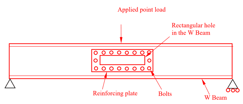
2023-01-30-10.25.03_xi1kqx.png


I have made sure that:
- The minimum bolt edge distance is respected.
- The minimum bolt pitch is respected.
- The bolt resistance is sufficient to resist the point load.
- The bearing resistance of the steel beam bolt holes are sufficient to resist the point load.
- The reinforcing plate is more thick and has a higher Fy and Fu than the web of the beam.
- There are 2 reinforcing plates on each side of the web, so it is symmetrical.

Is there anything else I should consider?
 
Replies continue below

Recommended for you

Thank you for informing me of this document JoshPlumSE. I checked this document. However, I think my example should have included a view through the reinforced hole, since after the reinforcement, there is no hole:

2023-01-30-11.09.36_iumoir.png


Sorry for the confusion. I think the AISC Guide 2 does not cover my precise example of a reinforcement.
 
I would show how the shear is distributed between the beam web and the "patch", show the shear forces at three sections (at the CL, just beyond the cut-out, and somewhere between these two sections).

"Hoffen wir mal, dass alles gut geht !"
General Paulus, Nov 1942, outside Stalingrad after the launch of Operation Uranus.
 
If you install this on a beam that's already in place, load distribution is not the same as if the modified beam is installed and then loaded.
 

- If there is no hole , in this case this is not reinforcing of a hole but closing an existing hole .. You may calculate the shear at bolts with simple rules of solid mechanics..


If you put garbage in a computer nothing comes out but garbage. But this garbage, having passed through a very expensive machine, is somehow ennobled and none dare criticize it. ( ANONYMOUS )
 
I don't love this as a bolted reinforcement scheme. Can you weld the plate instead? While I get the impetus for symmetry, I feel that you can do this one sided and make the reinforcement more cost effective in doing so.
 
KootK, I can't weld due to low resilience. Good point that it could have been one sided. The added cost of the second plate was so low that we decided to go for it to avoid any further analysis which would have cost more.
 
Logan82 said:
KootK, I can't weld due to low resilience.

Can you further explain the low resilience issue? If this is a fatigue thing, I'd just use continuous welding to deal with that rather than stitch welding. In many respects, I'd consider a welded solution to be more resilient than the bolted solution.

Logan82 said:
The added cost of the second plate was so low that we decided to go for it to avoid any further analysis which would have cost more.

I agree for the bolted option since the two sided setup:

a) Adds nothing to the fastening cost and;

b) Gets you double shear on your bolts which is sexy.
 
Thank you all for your advices.

JStephen, the beam will be installed on its 2 supports when we will install the patch, but it won't be loaded when we will install the patch.
 
KootK said:
Can you further explain the low resilience issue? If this is a fatigue thing, I'd just use continuous welding to deal with that rather than stitch welding. In many respects, I'd consider a welded solution to be more resilient than the bolted solution.
The reason is that the charpy results were low, and the beam will be used in cold weather. So we want to avoid creating cracking initiators. Welds would produce crack initiators. We have a whole analysis and procedure done to mitigate this low resilience issue, and it includes to avoid welding the beam.
 
Logan82 said:
Welds would produce crack initiators.

I don't believe that is true of continuous fillet welds. In this respect, I'd tend to have more concern for the bolt hole slop that has to be taken up before the bolts fully engage. If you're married to doing this as a bolted setup, I'd give some thought to doing it slip critical.

Logan82 said:
Is there anything else I should consider?

1) You'll need to move about half of the point load through each of the vertical bolt groups (3 bots) on either side of the reinforcement plate.

2) I would assume that the entire point load needs to make its way into the reinforcing plate over just the two or three bolts directly under the point of load application. That would apply at the top of the reinforcement plate. You might be able to justify the engagement of a few more bolts at the bottom of the reinforcement plate.

3) I'd carefully consider the potential need for stiffeners under the point of load application, both for web stability and load distribution.
 
KootK said:
I don't believe that is true of continuous fillet welds. In this respect, I'd tend to have more concern for the bolt hole slop that has to be taken up before the bolts fully engage. If you're married to doing this as a bolted setup, I'd give some thought to doing it slip critical.
This. So much of this.

Bolts in bearing only work once they have slipped. This design gives no room for the bolts or ply to move in order to engage the load. If your bolt holes are 2mm oversize then you would need the top of the web to deflect 2mm before engagement occurs and probably 3mm before proper bolt bearing occurs. In the mean time other parts of your web has already yielded.

I'll go as far as saying that this bolted design with non slip critical is not structurally suitable for the task.
(Feel free to prove me wrong!) [swords]
 
I would look carefully at all the constraints around the hole. In all my years I have never seen and existing application where there is not a lot of things in the way. If you want accurate holes they will need to use a mag-drill. That is not small. I would look carefully at my weld options.
 
Could you use two angles top and bottom, a little longer but not connected to each other?
 
Logan82:
You said..., “The reason is that the charpy results were low, and the beam will be used in cold weather. So we want to avoid creating cracking initiators. Welds would produce crack initiators. We have a whole analysis and procedure done to mitigate this low resilience issue, and it includes to avoid welding the beam.” And..., 18 drilled web holes and their sharp edges and the square corners in the rectangular web cut-out and its rough cut edges, all in a fairly highly stressed region of the beam, aren’t stress raisers or “creating cracking initiators?” The uneven bolt bearing in/on some holes would cause very high multi-axial stresses, another big stress raiser, assuming enough movement/yielding could occur. The above “whole analysis and procedure...” seems suspect. The best mitigation would be the elimination of all of the above stress raisers.

You apparently took samples for charpy tests, hopefully the average of several tests; did you take samples to try to determine what the existing steel grade (ASTM spec.) or weldability is? How old is that existing beam? What beam section is it? You haven’t said it is not weldable.

You guys are always so coy when it comes to divulging the important design details about an engineering problem, instead showing an elementary engineering textbook drawing intended to teach one simple topic, as if all holes in beam webs where identical. Kinda like, 8" brick corbels, 10' long cantilevered channel beam with no bracing, and a 120' tall smoke stack are all the same. They are all cantilevers, except they sure as heck aren’t the same. How about some dimensions on the sketches, member sizes and mat’l. thicknesses, loads, moments, stresses, other pertinent engineering design info etc., etc., so we would have some idea of the proportions and magnitude of the problem.

I would put the point load on a longer, thicker base plate on top of the existing beam to distribute it better over the top tee section of the existing beam. Then, I would cut a piece of web pl. to fit into the existing rectangular web hole. I would prep. 45̊ bevels on one side, leaving an 1/8th inch land on the bevel. I’d make a weld pass or two from the bevel side, then back gouge the far side to sound weld metal and fill that gouged groove. Then, return to the first side and complete the bevel weld, and grind all the welds flush. I would UT the welds, and I’d have a weld fit for service on the tension flange on a highway bridge plate girder. Welds are usually not “cracking initiators,” when done properly, but many poor details and engineered conditions are.
 
Note: I do understand that the AISC design guide doesn't cover this exact form of reinforcement. But, the theory and procedures that are there should be helpful.

For example:
a) The method for computing moment and shear interaction as presented in 3.4.
b) Moment capacity for reinforce openings per section 3.5. Though this would have to be modified for the type of reinforcement you're planning.
c) Section 3.7 talks about how far the reinforcement must extend beyond the opening.


Cold applications and fracture mechanics are not my specialty. Though I will say, that I would think (based on my memory of the college fracture mechanics class) that introducing 18 bolt holes in the web sounds like more of a potential fracture issue than a properly done weld. Especially since you'll have a high stress concentration if one of the bolts is bearing and the others are not.

Of course, if you know you cannot get a proper weld done (due to location, labor issue, weather or such), then I understand. I've worked on a lot of petrochemical projects where a field weld would not be allowed under ANY circumstances because it had the potential to take down the entire refinery.
 
Thank you all for your inputs. It is really appreciated.

KootK said:
1) You'll need to move about half of the point load through each of the vertical bolt groups (3 bots) on either side of the reinforcement plate.
Just to make sure that I understand what you mean: Do you mean that the 3 vertical bolts must resist half the point load? If so, I already checked and 1 bolt can resist half the point load (it's overdesigned).

dhengr said:
And..., 18 drilled web holes and their sharp edges and the square corners in the rectangular web cut-out and its rough cut edges, all in a fairly highly stressed region of the beam, aren’t stress raisers or “creating cracking initiators?
It was missing from my drawing, but in reality there are circular holes at each corner of the rectangular hole. The idea behind this concept was that circular holes would bring less crack initiators than welds, but I may be wrong.

BAretired said:
Could you use two angles top and bottom, a little longer but not connected to each other?
I can't picture it. Can you show me a sketch of what you suggest?.

JoshPlumSE said:
Note: I do understand that the AISC design guide doesn't cover this exact form of reinforcement. But, the theory and procedures that are there should be helpful.
For example:
a) The method for computing moment and shear interaction as presented in 3.4.
b) Moment capacity for reinforce openings per section 3.5. Though this would have to be modified for the type of reinforcement you're planning.
c) Section 3.7 talks about how far the reinforcement must extend beyond the opening.
Good point, thanks. Concerning section 3.5, how can you modify it with the type of reinforcement I am planning?

I will analyze the other concerns you have shared me and get back to you.
 
Logan82 said:
I can't picture it. Can you show me a sketch of what you suggest?.

I prefer welds, but this detail could work with bolts or welds, if you have access to accommodate the angles.

Capture_sx4uc6.jpg
 
Status
Not open for further replies.

Part and Inventory Search

Sponsor