Continue to Site

Eng-Tips is the largest engineering community on the Internet

Intelligent Work Forums for Engineering Professionals

  • Congratulations IDS on being selected by the Eng-Tips community for having the most helpful posts in the forums last week. Way to Go!

Removing (deleting) elements surrounded between 2 consecutive time steps 1

Status
Not open for further replies.

Amir88

Mechanical
Aug 26, 2019
2
Hello,

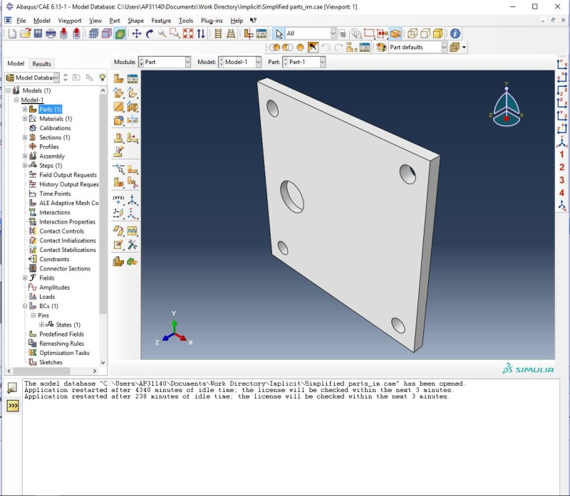
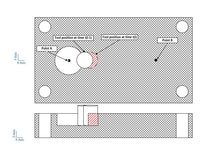
I am trying to simplify a cutting process (milling) in which there is a disturbed uniform force in Z-direction acting on a workpiece (representing my tool force), moving from point A to B in a straight line in X-direction. Instead of dealing with subroutines such as DLOAD and VLOAD, I have decided to simulate it in some increments. I have attached the image of my work below.
The workpiece is clamped at the corners to four location pins (U1=U2=U3=UR1=UR2=UR3=0).
My question is, how can I practically do such a thing with ABAQUS? I'm new to ABAQUS and I know how check the "Element Deletion" box in "Element Type" window. (is this better to be done in Implicit or Explicit?)

Thank you in advance.
PIC_tx0uhy.jpg

pic2_b2gaiw.jpg
 
Replies continue below

Recommended for you

Abaqus can handle simulations with milling tool geometry included. In this case you can make it rigid and apply rotation as well as linear motion to it. Elements on the path of the tool can be deleted (I will describe the way it works a bit later). However this requires explicit solver to avoid convergence issues and can be difficult if you don’t have experience in auch simulations. I’m not sure if you can simplify this problem by applying moving force. I’m afraid that it may not represent forces from the tool properly. But if you’ve seen such approach in literature let me know and share this reference if possible.

Anyway you will need element deletion mentioned before. This is related to material damage. Elements are deleted only when they fail i.e. failure criterion included in their material properties is fulfilled. In the material definition window you can specify various damage initiation and evolution criteria. For milling simulation I would use Johnson-Cook model.
 
Thank you for your reply,

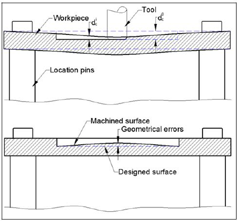
The thing is, my experiment doesn't exceed elastic domain. Therefore, I don't want to put plastic properties into my material properties and analysis. It's about milling a thin part with 6 mm thickness and 4mm depth of cut (DOC). Later on I am going to do API and make a loop between python and ABAQUS. In Python, I am calculating the cutting force in Z-direction according to the nominal (desired) cutting depth. Then, I receive displacement results from ABAQUS and see the errors. I use this simulated results to change my nominal DOC and calculate the new cutting force in Python and again use this new cutting force in ABAQUS and see the errors (because there is deformation, it usually cuts less material, 3.5mm instead of 4mm for instance). It keeps going on until an acceptable value. The other forces in other directions don't really matter for me, that's why I have decided to make this approach. Additionally, designing the whole tool is not my job. I am continuing someone's work and the reference has been shared below.

Nguyen, S. Q. (2016). Prediction and compensation of geometrical errors in milling process of thin components using a flexible configuration setup (Doctoral dissertation, École de technologie supérieure).
deformation_pcdgnh.jpg
 
Status
Not open for further replies.

Part and Inventory Search

Sponsor