Continue to Site

Eng-Tips is the largest engineering community on the Internet

Intelligent Work Forums for Engineering Professionals

  • Congratulations The Obturator on being selected by the Eng-Tips community for having the most helpful posts in the forums last week. Way to Go!

Removing failed elements from display 1

Status
Not open for further replies.

dogge92

Mechanical
Sep 11, 2015
8
Hello,

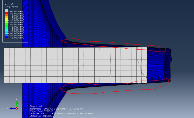
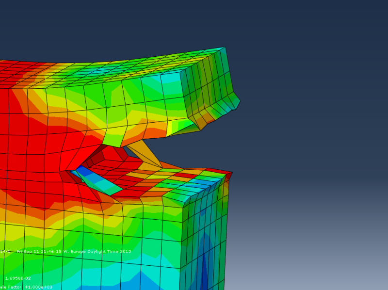
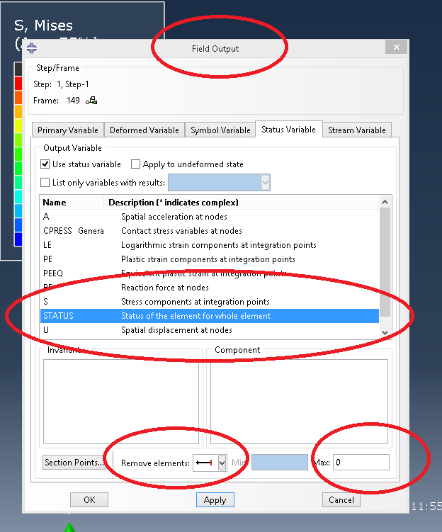
i have a problem with removing failed elements in abaqus. I am investigating the impact of a cylinder on a plate. The plate should be penetrated. I am using the Johnson-Cook-model and have assigned a value for "displacement at failure" under the option "damage evolution". I have also enabled the "element deletion" option and "status" in the field output menu. But the extremely distorted elements are still shown in the view port. Can somebody tell me what else i am supposed to do ? I have attached a screenshot of the problem so you can see what i mean.

 
 http://files.engineering.com/getfile.aspx?folder=c03ea7a7-c537-4bb4-b126-e967881b61ba&file=screen.PNG
Replies continue below

Recommended for you

Hi,
See attached. Does that work? If not then maybe they haven't failed.

remove_failed_ym41dk.png
 
No, unfortunately it doesn't work. According to abaqus the distorted elements havent failed but i dont understand why they didnt.
status_screen_vnhzof.png

 
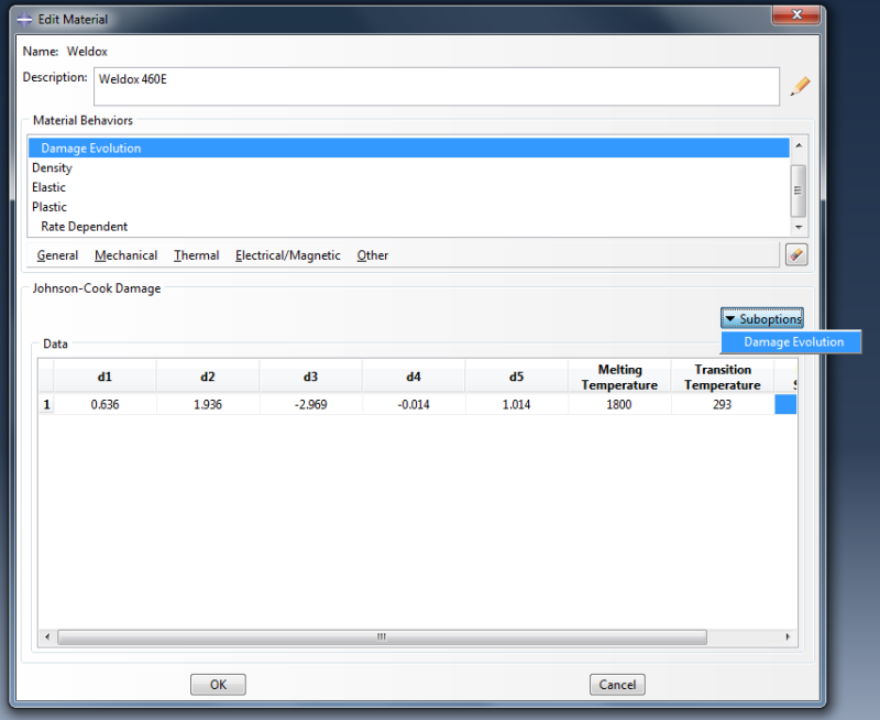
Then maybe it has to do with your material properties. Damage initiation, evolution and failure. Please post material data and maybe we can find out.
 
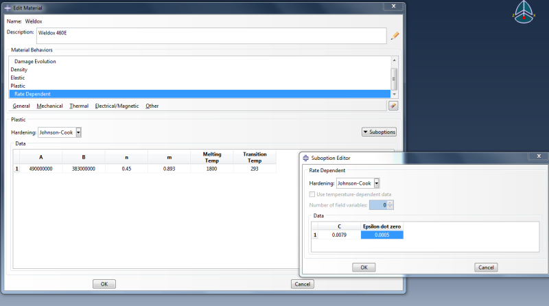
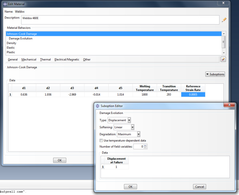
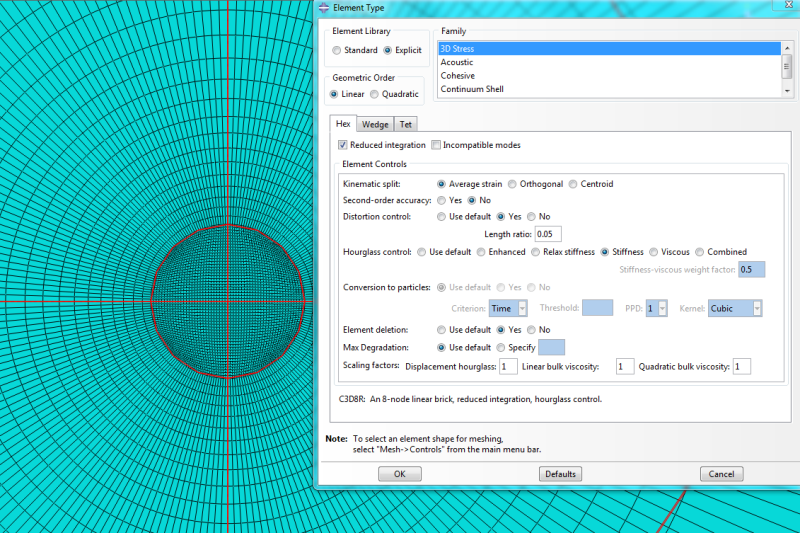
These are the material data and mesh attributes:
E modulus = 210 GPa
Density = 7850 kg/m³
poissons ratio = 0.33

data2_dwuuhs.png

data1_zw0fd5.png

data3_efysa7.png
 
and this is the material definition of the bullet. Its hardened steel thats why there is no need to define damage criteria.
data4_mmpp0b.png
 
I do not have CAE installed on my pc but I think there were additional options if you marked "Damage Evolution" and then clicked suboptions...
 
"Damage Evolution" is a suboption. There are no more "suboptions" after you have opened damage evolution.
data5_w6djwa.png
 
Hello,
I tried your material model and it worked fine for me. Elements are deleted. I am not qualified to comment on the material model's accuracy though.

I attached a test input file.

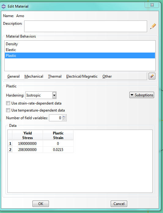
Oh yes, I made one modification to the "plastic". I might be using other units than you [mm, tonne, MPa].

fail_ttyh1z.png


Good luck!
 
Thanks for trying it out. I attached my input file, maybe you will find some differences between our models that would explain the result. i looked at your input file and realized that you have defined the material different than i did. i defined plasticity also with the johnson cook model, but you have defined it with just 2 stress yield values and strain values. Thats how i have defined the projectile. not the plate.
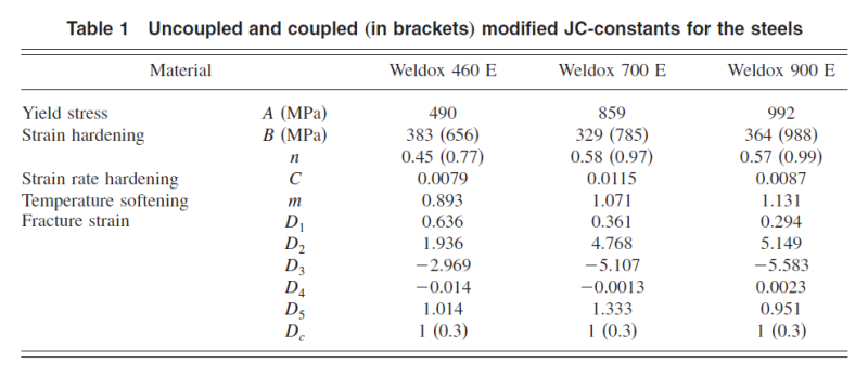
All this settings are from a paper i try to remodel. It's also strange that you have not enabled the element deletion option in the mesh module but the elements are still being eleminated. I will now use your material definition and let the rest be same to see if its just a material definition problem.
 
 http://files.engineering.com/getfile.aspx?folder=d9833381-fae4-4253-8e6b-0eeb726c8dfc&file=Job-impact-kane-grob.inp
i tried it with your material definition with and without "element deletion" but the result is the same. Really strange. You have 3 Field Output Requests instead of 1. Why ?
 
Hi,
I used the plastic definition that you showed in previous post. Element deletion is as you say (use default).
When I import your model it also says "Element deletion: Use default".

I just have one field output request. I think it just bacame 3 when you imported the model from .inp. Boundary conditions usually split up into as many DOFs that are constrained.

Could it be a problem with consistent units?
Should the displacement at failure be equal to 1 (Damage evolution suboption)?
 
I checked the unit consistency and found nothing.
Displacement at failure is equal to 1 because that's how it's noted on the paper. Look for D_c
Unbenannt_tqx0i6.png
 
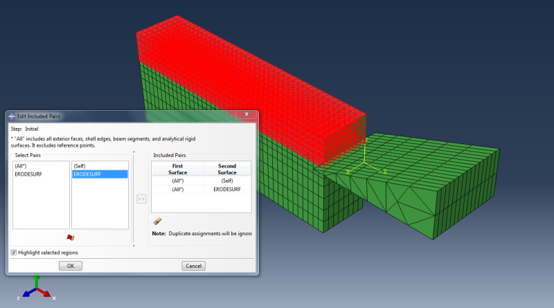
Stefcon, why did you set the settings for general contact the way you did ? i found out that when i remove these 2 included pairs the elements in your model wont be deleted either.
Can you explain me please what this setting means ?
Unbenannt3432_qeuhge.png
 
Hey,
Those settings are only to include the internal element surfaces. This will allow the wedge to make contact with all elements that comes in contact with its cutting edge. The surface "erodesurf" is a surface defined on all internal element surfaces. Remove it from the general contact and you will see why.

I actually got the idea from an impact analysis...

Cheers!
 
Status
Not open for further replies.

Part and Inventory Search

Sponsor