Continue to Site

Eng-Tips is the largest engineering community on the Internet

Intelligent Work Forums for Engineering Professionals

  • Congratulations SSS148 on being selected by the Eng-Tips community for having the most helpful posts in the forums last week. Way to Go!

Repair of Square Hollow Sections 1

Status
Not open for further replies.

12345abc6ttyui67

Structural
Jan 8, 2018
197
Hi,

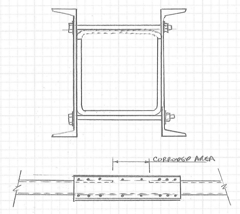
I have a 250x250x10 square hollow section (SHS) horizontal beam where the entire top wall has corroded over a length of approx. 200 / 300mm, e.g. the cross section now resembles a U rather than a square.

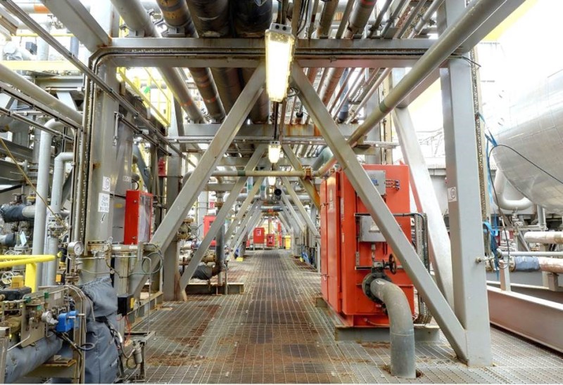
I am looking at potential repair options. The beam is on an offshore oil platform, so welding is not really a solution the Client wants.

Further, the existing loads in the beam are 'unknown' at this stage (I am trying to get hold of the original design report, but it's proving difficult). I therefore want to try and approach this to make the repair full strength, or "as strong as the original section". If this is impractical, I will need to do an analysis of the structure (which will be time consuming) just to find the loads in this beam, in order to apply a (potentially more practical) "non full strength" repair. By the end of the analysis, I of course might discover I need it to be full strength anyway!

So, I see my possible repair options as:
1) Welding a new cover plate to replace the top wall (least preferred by Client due to Offshore restrictions on 'hot work')
2) Bolting a new cover plate to replace the top wall (not preferred as introducing new holes / corrosion paths into the box, reducing section strength at bolt holes, hard to maintain seal to prevent corrosion inside the SHS, likely many bolts required to develop full strength)
3) Bonding a cover plate to the top wall (e.g. Belzona 1111 Super Metal as the bonding agent) (not preferred as no data on Belzona shear strength or fatigue life)
4) A composite wrap (e.g. FurmaWrap or Belzona SuperWrap) (Client has basically said No to this option right off the bat)
5) Any other options you kind ladies and gents may know?

Thanks.
 
Replies continue below

Recommended for you

What are the beam end connections? And how long is it? Can you shore and replace the beam entirely?

----
The name is a long story -- just call me Lo.
 
Here's an idea. It will take some figuring to determine the length of the channels and the number/size of the bolts.
You could also add some small tab plates on the back sides of the channels to fit with and further lock in the channels to the tube.

Tube_fix_bzdbow.jpg


Check out Eng-Tips Forum's Policies here:
faq731-376
 
Thanks Lomarandil, good suggestion, forgot to mention this in my first post.

The beam is welded either end to 250x250x10SHS posts, which are part of a large framework. The corroded beam in question is one of the lower beams in the structure, and has some of the lateral bracings attached, as well as supporting various pipe lines (which ideally are to remain in service). The beam is approx. 4m long, with inverted V bracings (also 250SHS) welded at midspan to the lower wall.

I had thought of shoring and replacing, however thought this would cause a few issues (none of which are insurmountable):
-> Full analysis of structure required to determine suitability of removing the beam (while structure in service) / to determine the loads in the shoring
-> Lack of significant other steelwork in the area to shore against
-> Requirement to temporary support pipes while the beam is removed
-> Likely hotwork required to reinstate the beam, which will be more significant than just welding a cover plate

I will toy with this idea some more though, as nothing is off the table yet.
 
Thanks JAE, I like this idea a lot and will definitely give it some more thought.

Just to clarify, was the intention of your sketch to torque the bolts to get a friction (slip resistant) face between the side wall of the SHS and the web of the PFC? Or were you thinking of site fitting the bolts to be 'snug' against the top and bottom walls of the SHS so they act like a sleeve / collar round the SHS?
 
Not friction.

Snug tight to get the bolts to simply bear on the existing tube - perhaps extending the channels far enough that the bolts work in couples to create a sort of rigid fixity at each end of the channels.
Also mentioned the tab plate idea to add to that fixed-fit concept.

Check out Eng-Tips Forum's Policies here:
faq731-376
 
If a section of the top wall is gone, I'm thinking the interior "floor" is not far behind, unless the corrosion protection when new was heroic.

As always a lack of pictures and drawings means the conversation begins 100 yards before the starting line, and possibly facing backwards.
 
In my opinion, you really need to know the loads in that beam.

Magnitudes may matter less than just knowing the direction of the vectors; this could save you some analysis time.

JAE's solution, for example, looks like it would work quite well for a beam in bending (assuming the concept of near-rigid fixity at each end of the beam is applied) but would not do much if that beam is loaded in tension.
 
jgKRI - very correct on the axial issue.

The only thing for axial is that if the area is much higher than needed for axial, then the channels do add somewhat to the effective kL/r of the section if detailed properly.
It may not get the section back to the original kL/r and axial capacity but would get you much closer than it is now with a missing wall.

Check out Eng-Tips Forum's Policies here:
faq731-376
 
a sketch of the local conditions would help...JAE's concept has merit but leaves the sealing requirement still to be addressed ....unless it is an unusual case, corrosion seldom is confined to a very discrete area.......
 
JAE said:
The only thing for axial is that if the area is much higher than needed for axial, then the channels do add somewhat to the effective kL/r of the section if detailed properly.
It may not get the section back to the original kL/r and axial capacity but would get you much closer than it is now with a missing wall.

I'd imagine you'd get a fairly sizeable increase in resistance to compression buckling, since you're basically preventing the existing beam's walls from deforming to the outside. Any buckling would have to consist of movement of the walls toward the center of the cross section.

This is all assuming that the bolts are not tightened enough to create a significant amount of friction- so that the channel/beam faying surfaces slip before the channel develops any real axial stress.

How would you handle calculating the capacity of this arrangement in compression?

Not assaulting the soundness of this idea- I think it's a very efficient method of reinforcement. Just trying to wrap my head around how you might approach estimating the arrangement's true capacity, and how accurate a calculation you could make. These calcs are out of my comfort zone.

WRT the sealing question- couldn't the repair place the channels on top of and underneath the existing beam, and use a sealant dispensed on the channel faces to seal the hole? You would want to remove as much of the existing corroded material as possible of course, and coat as much of the inside of the existing beam as possible before installing the channels.

By my estimation, for compression loads there's not a huge penalty if the channels are placed top/bottom instead of left/right; the one thing you would have to address is the possibility of fastener loss if things loosen. You'd definitely want a very reliable scheme to keep the bolt preload at the installed level and retain the nuts on the bottom.
 
SHS_Picture_ewtn7u.jpg


Thanks for the input everyone. Picture attached. The corroded section is under the black pipe to the left of the nearest light. There is insulation around the pipe (which can be removed) so access it not as tight as it first looks.

My current thoughts are to re-support all of the pipe work on a new beam which is underslung from the two RHS's sections on the left and right of the picture - this gets the pipe supports out of the way. I'm not too concerned about overall changes to the load paths in terms of global structure as it is still pretty close to the original design. Obviously I will need to check the RHS members for the increased loads, but I do not suspect this will be a problem. Note the lower pipe on the right is plenty clear of this option.

JAE's channel splice will need to account for the braces, but it just means a longer section of channel than that required to just bridge the corroded area. There shouldn't be a huge amount of moment anyways considering the braces, but without actual loads I am tempted to design the repair for the full section capacity (very easy to justify considering unknown loads). Yes, it will be overkill...

Tmoose - there have been some wall thickness tests carried out and it appears only the top wall is affected. I think the pipe support shoe has been been rubbing across the top of the SHS which has a) removed the paint, and b) trapped water etc. leading to accelerated corrosion. On my list of things to do is to get more points measured around the walls to check for other areas where wall thickness has been lost. Currently it looks as thought this will not be too much of a concern.

jgKRI - yes, I would be much more comfortable knowing what is going on. You are right JAE's solution doesn't pick up any axial loads, but I had thought about blind bolting his channels at a few locations to transfer any axial loads through the channels, or perhaps running the channels full length and having them connect to the posts. I'm keen to avoid trying to provide a full moment connection at the posts (capable of resisting the full section strength) as it will be hard to achieve. JAE's 'splice' to carry the moment over the corroded section, with some additional axial capacity should be easier to achieve.

SAIL3 - yes, sealing still to be addressed, however it would be much easier to achieve if the seal also does not need to be load bearing.
 
The offshore people whom I have met are totally anal about crevice corrosion, so I don't think a splint would make them happy.

They don't like much like HSS sections either, unless each end of each piece is cappped or plugged and seal welded and every weld is demonstrated gas-tight.

How about a big moment frame braced to, but separated from, the existing structure?
Maybe made of I-beams so the pipes can be tied down with I-Rod supports
... and the existing supports/shoes can be removed,
letting the existing beam continue to carry the electrical conduits,
say after filling it with tar or some goop of the customer's choice?


Mike Halloran
Pembroke Pines, FL, USA
 
MikeHalloran, yes, crevice corrosion is also a concern (since that's pretty much what got the structure in this condition to begin with). Definitely some kind of sealant would be required in the 'splint' option. I'd probably just coat the surfaces between channel and SHS with Belzona and use it as a sealant, rather than as any load carrying mechanism.

I had considered a new moment frame too, however I feel something really needs to be done to get the existing section back to design capacity too. It is part of a much larger structure carrying a lot more loads than shown in the picture. I wouldn't be comfortable leaving it as is without some kind of strengthening. I should add this is on an FPSO, so there are lateral inertia loads which this frame will be resisting.

I'd also thought about adding a new moment frame and somehow tying this into the ex. structure so the new frame is capable of carrying the design capacity of the existing frame, but considering the offset and capacity required, the connections get tricky very quickly.

I think some sort of strengthening will be better in the long run than a new frame. Just my thoughts though...

What it really boils down to is how much info. the Client can provide in terms of existing utilisations, and if not enough info., whether they want to pay me to re-design the pipe rack to determine actual loads for the beam. Otherwise I don't see much option other than belts-and-braces "make it as strong as the original design".
 
It looks to me like the repair will need to be repeated for each of the "bents" in the picture with the same pipe support detail = at least 3 or 4 more times .
 
Tmoose - not sure what you mean by "bents", however we have had the entire pipe rack surveyed across the entire FPSO and there is only this one location which is an issue. All other members / supports have been inspected and are OK.
 
RandomTaskkk:
I’d want to know that I had solved/corrected whatever caused the corrosion in the first place, or you haven’t really solved the problem. Your idea of retained water under the pipe support base pl. is probably right on the money, but where is the moisture coming from? You can see rust marks on several other locations on the pipe rack horiz. members. We sometimes call each of those pipe rack frames a ‘bent.’ I would get with the client’s piping engineer and see if the pipes would tolerate being moved up (vertically) temporarily. If you think JAE’s detail will work, this vert. pipe movement would be permanent, 3-4" vert., and cause a serious high spot in the piping.

If you moved 18-24" in the direction out of your picture, away from the fixed frame, and placed a beam parallel to the fixed frame, and 4-5" below the piping, and as long as the beam member on the fixed frame. This temp beam would fit laterally btwn. the two 4x10 (or whatever) RHS members which are pointing out of the photo, btwn. two bents. Atop this temp. beam, band sawn oak saddles, wood blocks and wedges fit up under the various pipes to snug the pipes up, on the temp. beam. Work from the middle out in both directions. Then the temp. beam can be jacked up 4, 5-6" to lift the pipes and their saddles up off the bent in question. Shore the temp. beam for the duration of the work, from below and to the 4x10 RHS members.

I would break form a piece of .5" stl. pl., 250mm + wide on the inside, with turned down legs about 5" long to just fit over the existing horiz. 250x250 member, and only a couple inches short of the existing member length. Pre-drill bolt holes in the legs for one of several different blind bolting systems. These holes will also be a template for drilling the existing SHS webs, in place. This downward facing channel shape should be able to be slid into place if the pipes are lifted about 4". Then the pipes can be set back down for the drilling and the bolting to act as part of the hold down needed for this operation, but maybe not. You now have a system which adds a new top flange and bolting can be designed for whatever shear flow is needed to make this a true built-up member. Maybe you shouldn’t set the pipes down all the way, so as to keep the horiz. SHS unloaded until the bolting is completed. Gotta think on this a little more. The worst loading on these members may be when they act as lateral loaded frames, those are some pretty sizable braces, if their size really indicates their loading possibilities.
 
This is a bit of an outside the box idea, but hey I'll throw it out there... Hilti reps have been telling me for a couple years about their direct-fastened threaded S-BT studs developed specifically for the offshore market where there are corrosion concerns and welding restrictions. Although these studs were developed for attaching appurtenances and whatnot, couldn't one conceivably use them to attach flitch plates/channels a la JAE's detail?

These studs have about a 500-600 lb allowable shear capacity with safety factor of 5 per Hilti:


Pros:

You can keep the reinforcement flush with the original beam and not have to mess with the pipes.
No hot work, no grinding off paint required.
Published allowable values with backup static and dynamic testing.
Stainless steel and composite studs available.

Cons:

Not the intended use of the fastener and hasn't been tested for this type of structural applications.
May not have the shear capacity needed to develop the strength of the required reinforcement.
 
dhengr - yes, the root cause is something I plan to address in the 'final solution'. I am thinking along the same lines as you I think. I intend to add a new beam slung below the two RHS beams which come 'out of' the picture at the left and right hand sides. This could be temporary, however I think I will just make it permanent (it means less work overall offshore as they don't need to double handle it). I will design this beam to suit. On top of this beam (which I picture probably being a UB or UC section) I will get 'wear plates' (say 20mm thk) welded on during fabrication at each pipe support location. I will then add replacement pipe shoes / supports on top of the wear plates with some packers to make up to the current elevation of the pipework (e.g. no raising of the pipe work required). I might even add some PTFE type pad to prevent steel on steel rubbing, and break down of the coatings. I need to mull that over some more though.

Once that's done, I'll get the pipe shoes / supports on the corroded SHS cut off and removed, leaving the top wall of the SHS clear.

This will give enough clear space between the top of the SHS and the remnants of the old pipe shoes to add any of the strengthening options touted so far, and also frees up space to clean up the corroded section, dry it out, seal etc. This also means (assuming the strengthening fits in the space) there will be no need to adjust pipe elevations or add 'high spots'.

Your idea of a channel shape along the entire top flange is good, and will definitely make getting the required shear strength to take the moment through from the SHS into the channel easier. I think I would need to torque the bolts in this case though to get friction between the channel toes and the SHS walls, as the slip in the clearance holes before the bolts go into bearing may be too much (e.g. the channel would only be effective once the slip was taken up by loading and deflecting the ex. SHS). I will think on that some more. Torquing might well be OK anyways, I can easily check whether the SHS top wall buckles under the preload.

Yes, I also expect the lateral loading in the whole frame will be critical for the member design, I don't think the vertical load from the pipes will amount to much of the total. The braces are probably way over designed, but it's hard to know without getting the existing report, or crunching the numbers myself.

I think I would then leave it like this - all pipe supports relocated onto the new beam, and the existing SHS made good via whatever option is picked. Sure, there is a small change in the load path (e.g. support loads are now carried via the RHS) but my instinct says this should be (still need to calc it) a small overall increase to stresses in the RHS, and fairly easily justified.

bones206 - I'll take a look at those hilti fixings in more detail. I've used them in the past for 'non-structural' applications. Gut feel is they will struggle with what I'm trying to acheive in this instance, but will double check capacities for them and see.

On another note, I met with the Client yesterday who has said they will try and dig out the ex. reports, but felt they may not be available, and even if they were, might not be sufficiently detailed to pick out individual member loads / load cases. They didn't seem overly concerned with the 'make it as good as it was' approach and are more interested in a robust solution that will reinstate the original design.

 
At the moment I can not see a permanent fix without some welding involved just based on the requirement of sealing the hollow members....I have no experience with Belzona and if it is a permanent seal or just durable...
I would guess that this is not the first time that welding was done in a challenging environment and that standard methods have been established to perform it safely and would investigate that....
I would ask the owner if he wants a temporary fix with periodic inspections or a permanent one which probably involves welding....
Because of the marine environment and use of hollow members I would think it is a critical element of the design to have a permanent seal.....

 
Status
Not open for further replies.

Part and Inventory Search

Sponsor