Eng-Tips is the largest engineering community on the Internet

Intelligent Work Forums for Engineering Professionals

Repair of Tank Bottom API 653 - installation of a replacement bottom over an existing bottom 2

Status
Not open for further replies.

Mehrdad777

Industrial
Sep 15, 2022
3
0
0
ES
Hello

We want to repair a tank with 67m diameter and 16m height. Client wants double bottom for leack detection. ( according to API 653 section 9.11 .2.1)
The shell shall be slotted with a uniform cut made parallel to the tank bottom and I need to calculate size welding C-Clips to the tank shell.
Look like this foto :

Corte_envolvente_xut5eu.jpg


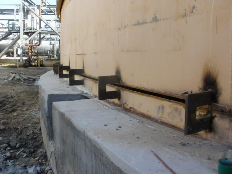
How can i calculate size of it?
I have to consider forces of wind, weight of empty tank and what more?
What source can I use for this calculation? for avoid shell buckling during API650 tank repair
 
Replies continue below

Recommended for you

Those clips, generally 3/4" thick and on roughly 5 foot centers are OK by inspection and experience. Calculate the vertical and horizontal forces using all the dead, construction, live, wind, snow, seismic factors combined per API 650 (I would not worry about thermal loading), possibly utilize duration factors from ASCE. FEA might show local overstress but this practice has been done thousands of times without incident or damage or apparent weakening of the tanks. The worst that happens is that a clip collapses and the tank settles an inch which is a big "so what".
 
Hello dear IFRs,
Thank you so much for your reply.

AS you know, there is rarely we have all the dead, construction, live, wind, snow, seismic factors combined per API 650 in the same time, for this reason, an accident didn´t happend.
In my case, I can´t rely on this experience because my tank is so old (1965) and first shell course has a thikness of 34mm. This tank weighted almost 600 tons. I don´t want to risk and live rest of my life in jail. [bigsmile]

In the company where I work we do not have any software for the calculation, so I need to size this support manually.
Is there any handbook or an example which I can follow?
Thank you so much.
 
I would stick with basic engineering principles, make free body diagrams, get the primary axis loads, then check the shear and bending stresses in the clip, and tank shell, then weld strengths.
 
Well I have to ask why are YOU doing this?

The best thing experience gives you is to know when you don't know and at that point you find people or companies that do.

I can't see how you're going to be able to prove this as you don't have all the data.

IFRS has that experience. Other companies who build and repair tanks all year have this experience. Use it. IMHO.

Remember - More details = better answers
Also: If you get a response it's polite to respond to it.
 
For tanks of this age the construction materials were prone to laminations, therefore, checking the attachment locations for laminations would generally be recommended. Probably less necessary with such uniform load distribution but for tank jacking points this would definitively be recommended.
 
Dear IFRs, Thank you so much for your response. I did all you said. I considered a figure for my C-clip in SOLID WORKS and made a model in ANSYS WORKBENCH with all loades. Result is shear and bending stress and if they are less than allowable strees of material of C-clip then design passed.
I'm trying various design for C-clip and I will upload results here for share to all.

Dear BJI, Thank you so much for your response. Really good point of view. I definitely consider it in this project.

Dear LittleInch, Thank you for your response. I consider all you said.
 
Status
Not open for further replies.
Back
Top