chris.hsi
Mechanical
- Mar 25, 2020
- 4
Hi there,
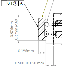
I've been working with these .6mm image sensors for a few months, trying various methods of handling them. My project is to epoxy this image sensor (.575mm square x .195mm) so it sits square to a hypo tube that encases the sensor cable. The hypo tube will be filled with epoxy. The cable is soldered onto 4 .13mm solder balls. I have used precision 3D printing and laser cut parts to locate these sensors in the past. I am hoping for ideas on how to square and locate such a small part for an operator to epoxy into place. I am currently thinking of using a laser cut fixture (hold the sensor square in place) mounted to a micrometer table for fine adjustment, then lowering the assembly onto the sensor. That would mean I need a precise way to hold the hype tube square.
Any concepts come to mind for squaring tiny parts?
Thanks!

