Continue to Site

Eng-Tips is the largest engineering community on the Internet

Intelligent Work Forums for Engineering Professionals

  • Congratulations IDS on being selected by the Eng-Tips community for having the most helpful posts in the forums last week. Way to Go!

Replacing 100 x 12 mm copper bus bar with 2 of 50 x 12 mm copper bus bars 3

Status
Not open for further replies.

edison123

Electrical
Oct 23, 2002
4,463
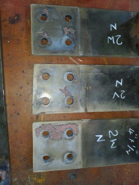
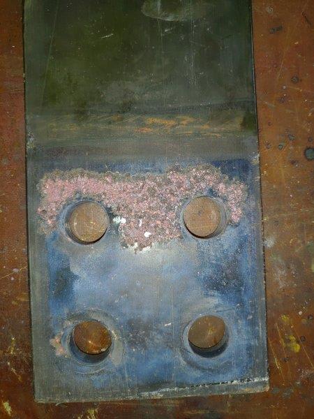
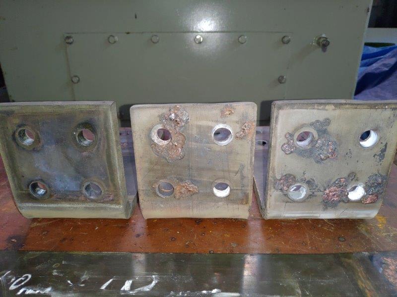
The contact area damages in 2000 A bus bar with 100x12 mm copper bus with four M12 bolts with 100 mm overlap at top and bottom.

Pitting_1_lg6y5j.jpg


Pitting_2_vrvwtx.jpg


Pitting_3_gn1tvm.jpg


Will replacing the 100x12 mm copper bus bar with 2 of 50x12 mm copper bus bars would help in reducing these contact area damages? The no. of bolts will remain the same at 4 of M12.


Muthu
 
Replies continue below

Recommended for you

Edison,my view is the overlap contact current density should be limited to about 0.8 A/mm2 ( better 0.5 A/mm2)in air. I don't think 2nos 50x12 mm will improve the situation. A better solution - improve the contact surface by machining; silver plate or tin plate the contact surface; use Beleville washers as shown in the guide (fig 70).
 
prc

The present contact area is 1 of 100 x 100 mm.

The proposed area is 2 of 50 x 100 mm and hence the contact area remains the same.

The cited article (6.3.2.1) also says plating may not be a good idea.

It is not normally recommended that the surfaces of copper-to-copper joints are plated unless required by environmental considerations. In fact, plating may reduce the stability of the joint because, as soft materials, the plating may flow at elevated temperatures leading to reduced contact
pressure.


However, to ensure a long service life, a contact aid compound is recommended to fill the voids in the contact area and prevent oxidation or corrosion. Many proprietary compounds are available or, if none are available, petroleum jelly or, for higher temperatures, silicone vacuum grease
may be used.


This is confusing since I have always silver plated or tin plated the copper interfaces.

Muthu
 
The areas where the copper appears to be melted are the low resistance contact points between the surfaces where current is actually flowing. The blue areas are oxidized and there is probably a microscopic air gap. Bright copper indicates no oxidation due to exposure to air when hot. Those areas were probably weakly welded together. Adding more contact area in parallel to the current path would be a good thing.

Surface flatness, stiffness, and uniformity of clamping pressure are all important to uniformity of current density across a contact area.
 
What about using an electrical inhibitor joint compound?
A good installation practice recommends its use to improve the electrical connection between metal parts such as the busbar presented. This type of product is an oxide-inhibiting compound for preventing galvanic corrosion and enhancing the connection in electrical joints.
Also make sure to use the proper hardware assembly (bolts, nuts, washers, etc) with the torque recommended by the manufacturer.
 
"It is not normally recommended that the surfaces of copper-to-copper joints are plated unless required by environmental considerations" In your case environmental conditions call for a coating. If contact temperature is not exceeding 100C, tin coating is enough. But if it goes above, silver plating is ideal. Considering the contact area provided, it looks like temperature may not exceed 100 C. Please make sure Belleville washers are provided to take care of uneven expansion of steel bolts and copper bus bar thickness. More than anything else, contact pressure decided the current transfer capacity.
 
Compositepro - Doubling the contact area by splitting the thickness of connecting bus bars and bolting them through both faces wherever possible is also being thought of.

cuky - Any suggestions for the electrical inhibitor joint compound? Galvanic corrosion between copper to copper ?

prc - It's a clean environment in a tyre maker. Belleville washers are in the mix.

Muthu
 
Hi

Well I don't think that changing from 100X12 is a good idea, if I understand correctly you will have two bolts in each copper section of 50mm, assuming that I would be concerned about short circuit forces on the copper joints should a fault occur, in addition the original joints would have gone through various tests like temperature rise when running with continuous current etc, in short you are altering the design of the equipment which might make any insurance invalid.

“Do not worry about your problems with mathematics, I assure you mine are far greater.” Albert Einstein
 

NO-OX-ID Link is recommended by the USA Bureau of Reclamation for Electrical Connections of Power Circuits (FIST 3-3 11/91)- This is a grade "A special" petroleum base compound with higher melting point, higher oxidation resistance and better weathering characteristics than petrolatum. It is widely used for copper-to-copper or bronze-to-bronze bus connections.

Caution should be used plating the busbar or using products such as Pentrox "A" or Alnox based on zinc particles since they cause a poorer connection due to the lower conductivity.

Quoting the Copper Development Association Publication 22 -Section 6.3.2.1: "It is not normally recommended that the surfaces of copper-to-copper joints are plated unless required by environmental considerations. In fact, plating may reduce the stability of the joint because, as soft materials, the plating may flow at elevated temperatures leading to reduced contact pressure. However, to ensure a long service life, a contact aid compound is recommended to fill the voids in the contact area and prevent oxidation or corrosion. Many proprietary compounds are available or, if none are available, petroleum jelly or, for higher temperatures, silicone vacuum grease may be used."
 
Dear Mr. edison123
1. I noticed:
First image-- left palm, no "electrical contact point" around 4 bolting holes,
middle palm, 3 points,
right palm, 3 points.
Second image--top palm, 3 points,
middle palm, 1 point,
bottom palm, 2 points.
Third image--only 1 palm-- top left and right, 2 points,
bottom left, 1 point.
Note: "electrical contact points" are shown by [rough/pitted surface] while the "air gaps" are shown in blue smooth surface.
2. From the above three images, it is evident that [none of them] having good "electrical contact points" around [all four bolting holes]. Possible cause: [uneven tightening torques] between the 4 bolts. Action to be taken: Check that [all four bolts] are tightened [evenly with equal torque].
Check: Bolt size M12 grade 8.8 or higher, nut grade 8 or higher. Use big 28mm or bigger width thickness 2.7mm or thicker washers. In addition, use Belleville washers are highly recommended. Tightening torque 45Nm [evenly for all 4 bolts].
3. Us of electrical inhibitor joint compound is superfluous. Silver-plating or tinning is
unnecessary in normal indoor dry conditions.
4. Opinion: replacing the existing single (100x12) by (2x50x12) bar (may not?) solve the problem. Look into improving the "electrical contact point" area is the essence.
5. Suggestion: File the whole palm area smooth including the pitted and unpitted areas. Using the existing (100x12) bar and take extra attention on the [even tightening torque].
Attention: Make sure to use a calibrated "torque wrench"!.

Che Kuan Yau (Singapore)
 
Perhaps these holes were punched rather than drilled. That would cause significant distortion of the plate flatness and explain the lack of contact around the holes.
 
Thanks cuky. I will check it out.

Thanks che. I am also thinking of not using any plating. Any reason why 2x50x12 mm may not work? We have seen proof 1x100x12 mm did not work in this case.

Compositepro - The holes look like they are drilled, not punched.

The pics I posted here are of the neutral connections. The same issues are found on the phase links also.

One thing I noted is all these pitting damages and overheating marks have occurred on the connecting busbars only. The transformer 415 V winding copper of 1x100x12 mm is still in good condition. And there are no signs any plating in the transformer copper.


Muthu
 
Dear Mr. edison123

Q1. Any reason why 2x50x12 mm may not work? We have seen proof 1x100x12 mm did not work in this case.
A1. If you sandwiched the palm between 2x (50x12) bars, in theory the "apparent contact surface" would be 2x (50xL)mm2; seems to be equal to 1 bar with contact surface of (100xL) mm2. What is more important is the "electrical contact point" where the current is flowing through. The other areas are "air gap" where almost no current flowing through. Filling up the "air gap" with whatever inhibitor joint compound is superfluous. Increase the "electrical contact points" = lower the "contact resistance" is the essence. Increase tightening torque would increase "electrical contact points" = lower the " electrical contact resistance". Reference (Copper for busbar Pub 22) by CDA.

Q2. " .... all these pitting damages and overheating marks have occurred on the connecting busbars only. The transformer 415 V winding copper of 1x100x12 mm is still in good condition ...."
A2. This is also evident that the problem is not due to the "apparent contact area" but the tightening torque is the essence. Therefore, replacing it with 2x50x12 mm bars may not? solve the problem.
Proposal: Tighten the 4 bolts evenly to the correct torque. Measure the contact resistance with low-resistance uohm meter with current say 500-1000A DC, using [4 point method]. Production of 500-1000A for a very short (say 2s) duration can be done with a 12V car battery, in case the uohm test set set is not available at site.
Attention: The small hand-held low resistance 4 point test sets which circulate current much lower than 100A is NOT suitable for this application.

Che Kuan Yau (Singapore)

 
Che - I think each 50x12 with two bolts would give better contact pressure than one 100x12 with 4 bolts since the latter will flex the copper easily and hence create poor contact.

Muthu
 
Edison,12 mm thick semi-hard copper busbar is not flexible and hence no advantage with 2 numbers 50 mm busbars. Your statement transformer bushing palm is clean and not corroded brings new angle. If it was due to loose contacts both sides should carry arcing marks. Is it due to copper quality of bus bar ? Can you check chemical analysis of it? Did you check the contact temperature with any infrared scanning?

My suggestion- check the quality of bus bar. If Ok, mill the contact surface. Tin the contact surface. Transformer bushing palms are normally tinned.(not plated)Tyre factory may be polluted with fumes?
 
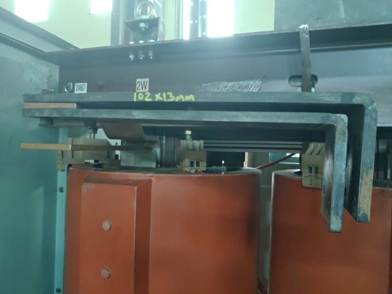
Old outgoing phase busbar (Inverted L shape) - 2x100x100 = 20,000 sq mm contact area

Old_phase_busbar_dclnwh.jpg


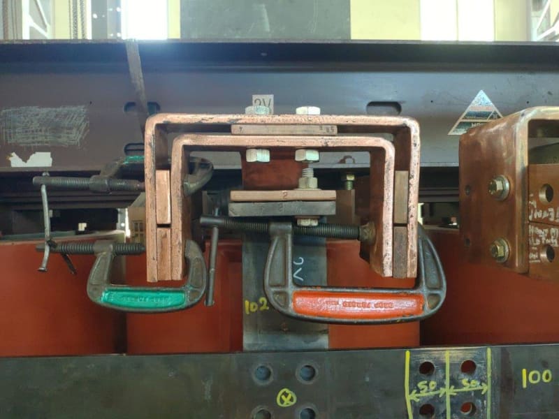
New outgoing phase busbar (Inverted U shape) - 8x50x100 = 40,000 sq mm contact area (Ignore the black neutral outgoing busbar directly below the phase lead).

New_phase_busbar_mszxbn.jpg


Muthu
 
Status
Not open for further replies.

Part and Inventory Search

Sponsor