Eng-Tips is the largest engineering community on the Internet

Intelligent Work Forums for Engineering Professionals

  • Congratulations waross on being selected by the Tek-Tips community for having the most helpful posts in the forums last week. Way to Go!

Required shrinkage reo in concrete water retaining structures 1

Status
Not open for further replies.

MrJB

Structural
Oct 7, 2021
15
0
0
AU
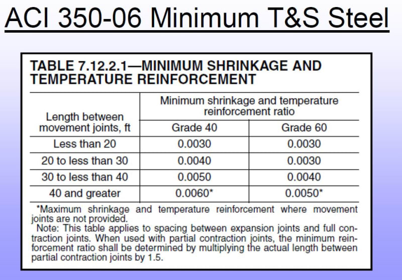
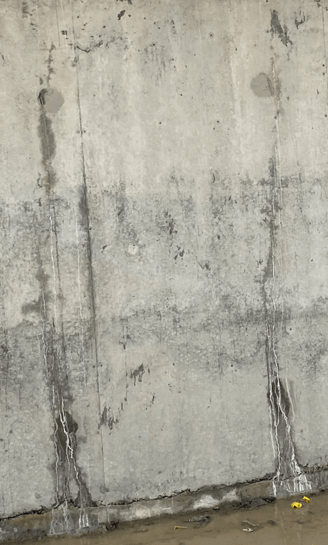
All, We have been asked to provide a forensic report on a brand new 30m diameter x 3 metre high circular water retaining structure that is leaking. Cracks have formed every 1-1.5 metres around the entire circumference and they have not self sealed after a week. The curved walls were poured in 2 halves and each one is about 100 metres long. There are 2 movement joints in the entire structure. The horizontal crack control reinforcement ratio is about 0.8%. Am not considering hoop stresses as there are the movement joints and a discontinuity of horizontal reinforcement. I have done some very basic calculations that show the stresses in the reo are about 25% higher than allowed in the standard yet my gut feel says it should be more than that.

Does anyone have any advice on calculating the exact amount of shrinkage reinforcement that should have been called up for this type of structure or any general comments?

Thanks in advance.
 
Replies continue below

Recommended for you

I've got an old spreadsheet to do this to BS 8007.

For thermal shrinkage cracking the calculations isn't too complex but you need to know more variables:

- thickness, strength, cover depth, proposed/actual reinforcement details of concrete
- temperature variables (seasonal variation. hydration peak and ambient)
- restraint factor
- thermal exp (standard value)
- max allowable crack width - from memory this is 0.2mm from BS 8007


Issues with the placement and additives will of course also need investigation.
 
The old ACI 350-89 gives a reinforcing ratio vs. movement joint spacing table. Sadly, like a lot of useful things, it's went away. But for joints 60 ft. apart and 60 ksi reinforcing, the ratio tops out at .005.
I don't understand the movement joints as you describe. When we design a circular structure, it's based on hoop tension and no movement joints are allowed. Maybe they tried designing it as a cantilever, but it's not an industry standard. Us old timers use the PCA document, "Circular Concrete Tanks without Prestressing." I'd recommend purchasing it.
I've seen the exact same thing on a tank (however, with no movement joints), where it cracked on a regular pattern of about 9'-0" spacing. It was designed correctly, so I can't explain it. Maybe the tension laps were done incorrectly.
 
 https://files.engineering.com/getfile.aspx?folder=c0b6c33b-5436-4b71-ab94-da7987944571&file=20230720092708.pdf
Below is the ACI 350 (2006) required T&S reinforcement schedule.

The newest version of ACI 350 requires a little more steel in regions where you have highly restrained concrete (corners etc..), but I don't think you get up to .008 reinforcing anywhere.

Capture_qp21lu.jpg
 
Cracking at regular intervals of about 3 metres is inevitable if the base is restrained, but control of the crack widths is what you want the reinforcement to do. 0.8% Ag should be plenty, but there are other factors. What size bars were used? God practice is to bunch several bars near the bottom of the wall to arrest the restraint crack at its source.
 
A week isn’t that long. Cracks in water retaining structures can take months to heal. Some never heal of course.

I went to an interesting seminar about a heavily reinforced basement that was intended to be watertight. The slabs cracked far more than they hoped, with groundwater leaking out. They gave the cracks a chance to heal, and then fixed the ones that didn’t.
 
Another week has past and it appears there is some self healing although further repairs will be needed.

I have just learnt that the 2 joints in the structure are construction joints (continuous reo and a scabbled face). Not sure what the designers intentions were though. The design could work as a cantilever arrangement yet as Jed mentioned in would be atypical. If the designers were relying on hoop stresses though I presume they would have used mechanical couplers for laps as the bars would be tension ties instead of lapping bars. As I have read here before there is a saying about how the concrete doesn't understand how it was designed..

The wall is nearly 200 metres long (30m diameter) without stress relief from a shrinkage point of view. The reo provide was quite high (N20s both faces @ 150crs in a 500 thick wall hence 0.8%) yet there must be a limit to the length of wall that this can be effective in. What is the equation/factors that govern the limit of the maximum length of wall?

Attached is a typical photo of the cracking pattern that repeats.
Screenshot_2023-07-24_104442_byi40n.png
 
la belle vie,

That is the definition of restrained shrinkage cracking. It is inevitable, but can be limited as to crack width by placing enough bars close to the bottom of the wall, which is where the tensile force is applied. In this case, I would guess the concrete had a high w/c ratio.
 
Status
Not open for further replies.
Back
Top