Continue to Site

Eng-Tips is the largest engineering community on the Internet

Intelligent Work Forums for Engineering Professionals

  • Congratulations waross on being selected by the Eng-Tips community for having the most helpful posts in the forums last week. Way to Go!

Residential Deck - Big Cantilever 2

Status
Not open for further replies.

JungleJoe

Structural
Jun 25, 2021
35
Hi everyone, thanks for reading.

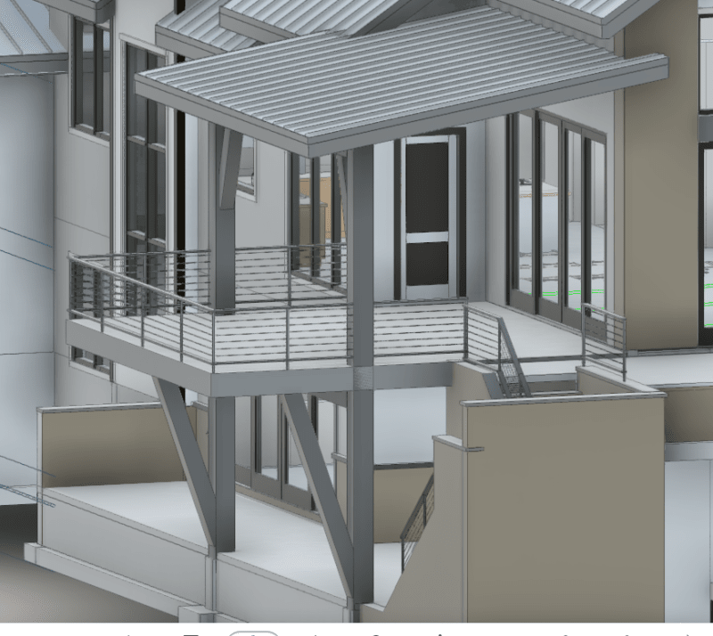
I am working on a residential project that has a deck with big (7' long) cantilever past the deck beam. The owner would like to use wood everywhere on this. See the pics below. Is there anything wrong with designing the deck joists to cantilever out that full distance? I've never designed a deck with a cantilever bigger than about 2' so going out just over 7' makes me nervous. I have run some numbers on some I-joists that seem adequate to me, but I'm wondering if any of you has experience with a cantilever like this. I will make sure to design the connection of the joists at the ledger. What potential issues have I neglected?

Deck_Pic_iuuieh.png

Deck_Pic2_dtix0w.png
 
Replies continue below

Recommended for you

I think exposure to the weather would eliminate I joists. Wood is problematic for decks at the best of times, as evidenced by the number of failures we see reported here. Cantilevered members just make it worse.
 
Thanks, hokie. I also ran a design using glulam members for the deck joists. I thought that might be strange, but maybe it's a good option?
 
I think the issue would be getting 18 foot dimensional lumber more than anything.

Why not cantilever just the edge beams since you've got that nice diagonal brace there to help and run your joists the other direction? That seems like a much more confident solution.
 
You can sister up the main joists with treated 14 footers. A lot of wood - I know!
 
Now that I look closer, my previous solution is no better since it still requires 20 foot joists.

However you could cantilever two edge beams utilizing that diagonal brace, and then also provide an end beam and then just simple span frame the joists in the cantilever area.

I feel that even 2x12 will feel bouncy at 7 foot cantilevers. Regardless of what the numbers tell you.
 
I would also be concerned about the "bounciness" at the tip of the cantilever. Also want to look at crushing/bearing stress of the member below the cantilever.
 
What about light gauge steel framing? Have you looked into that? (although that might be bouncy too)
 
Thanks for your thoughts everyone.

jayrod12 said:
However you could cantilever two edge beams utilizing that diagonal brace, and then also provide an end beam and then just simple span frame the joists in the cantilever area.
I thought about that, but then doesn't that create a moment connection from the brace where it meets the column? I could do that out of steel, but the builder asked if we could avoid steel if possible. I wasn't sure how I could get a good moment connection at that location with wood.

And yes, as many of of you have mentioned there is the issue of vibration/bounciness at the cantilever. I did mention the potential bounciness to the owner and he was opening to the idea of just putting a column at each corner to eliminate the cantilever. Not sure if the architect will like that though.
 

My initial thought was to eliminate the diagonal braces since they don't do very much... Other than durability and obtaining material, I don't see any issues with what has been presented.

Rather than think climate change and the corona virus as science, think of it as the wrath of God. Feel any better?

-Dik
 
I don't see why you'd need a moment connection for the diagonal. It's no different than a cross brace in compression.

If you mean for the beam itself, couldn't it just be considered pinned at the column with the connection designed and detailed for the uplift?

I think if the diagonal is going to be there architecturally, then you may as well use it to your advantage.
 
Ah, in my mind the beam loads straight down onto the diagonal which would create a moment arm at a distance d away from the column as shown below. But what you're saying is that the load from the beam will just become an axial compression load in the brace?

20210930_100333_eiyspn.jpg
 
As long as the brace is connected at both ends, there negligible moment in the brace. If the brace is connected to the post/column above the foundation, the lateral thrust will create a moment in the post.

Rod Smith, P.E., The artist formerly known as HotRod10
 
Bridgesmith has it. It's only compressive load in the brace. However it does impart a thrust load on the column if connected above the foundation, and also a tension on the floor beam to column connection in addition to the gravity aspects of the connection.
 
What are the mechanics of how that load does not result in a moment? Is there somewhere you can point me so I can read up on that? I believe you guys, but I'd like to be more educated about this because it's causing me to question everything I thought I knew about statics
 
Why not make it out of HSS and let the architect skin it with wood... seems a lot easier/safer/more robust long term.
 
JungleJoe - there is a moment, but it isn't resolved the way you're picturing it. A lot of it comes down to assumptions you make about the behavior. For instance, wood doesn't do moment connections very well. So the initial assumption should be that there is no moment resisted at any of the joints. Take a look at my quick paint sketch below. Do your FBD for the entire frame first. That will give you reactions at the two supports. Then look closely at the brace. The blue arrow is the applied load and the yellow arrows are the reactions within the frame. You'll have your brace in compression, the value of which will be higher than the applied load due to the angle. Then to maintain equilibrium you'll have a thrust force in the beam. Same thing happens at the bottom of the brace to get you back to a vertical reaction down at the foundation. But here the thrust puts your column into bending if applied above the base. This model is a bit simplistic. In reality, your brace will have an axial stiffness less than infinitiy, and its elastic shortening (and take up of any slop in the connection) will result in load sharing with the post through bending in the beam.

cantilevered_frame_cbnfid.png
 

Architects put those things at grade, just to get in the way... they're pretty clever...

Rather than think climate change and the corona virus as science, think of it as the wrath of God. Feel any better?

-Dik
 
Status
Not open for further replies.

Part and Inventory Search

Sponsor