Continue to Site

Eng-Tips is the largest engineering community on the Internet

Intelligent Work Forums for Engineering Professionals

  • Congratulations GregLocock on being selected by the Eng-Tips community for having the most helpful posts in the forums last week. Way to Go!

Resisting Torsion Due to Guy Wire Anchor Attached To Roof Framing

Eng_Struct

Structural
Sep 23, 2022
61
Hi Group,

I need to provide guy wire anchors to support the mechanical duct for wind uplift. The wires will be installed at roughly 45-60 degree angle and the guy wire anchor will consist of a round HSS tube with eye-bolt and base plate that will be welded to the roof beam top flange.

There is no access from below to install any additional members to take the torsion out. I wanted to confirm if the anchor is placed close to the joist shoe, is there a way for me to resolve the moment into axial force into the joist?

I have tried resolving the moment into horizontal tensions and compression force at the top and bottom flange - the top flange will be OK as it is restrained by the joists however there is nothing restraining the bottom chord for the entire span length and the horizontal force from the anchor moment will reuslt in a huge moment in the bottom flange bending in laterally.

Any suggestions or ideas will be helpfull. I have attached a sketch to explan the condition.

Thanks in Advance!
 

Attachments

  • Roof Anchor Sketch.JPG
    Roof Anchor Sketch.JPG
    55.6 KB · Views: 45
Replies continue below

Recommended for you

Change the stub’s geometry so the cable force pulls straight in line with where the top flange meets the joist.
 
The torsional resistance of W14 X 26 would be negligible . What is the connection detail of 12 in OWSJ purlin to the W14 X 26 ?
Can you shift the anchor locations to the columns ? Can Adding some stiffeners to the duct be an option so the spacing of anchors would be 21 ft 8in ?
A sketch would be useful showing the duct position, cable wires .
 
Last edited:
Change the stub’s geometry so the cable force pulls straight in line with where the top flange meets the joist.
This will require the stub baseplate to be directly at the top of the joist - I may have to consider vertical legs attached to the anchor base plate so that it can be connected to the beam on wither side of the joist shoe. I can also specify strengthening the joist shoe weld to the beam. This seems doable to me - Is this what you had in mind?


The torsional resistance of W14 X 26 would be negligible . What is the connection detail of 12 in OWSJ purlin to the W14 X 26 ?
Can you shift the anchor locations to the columns ? Can Adding some stiffeners to the duct be an option so he spacing of anchors would be 21 ft 8in ?
A sketch would be useful showing the duct position, cable wires .

The joist shoe connection is a welded connection to the W14 beam. As I had noted in my response to Tomfh, I can potentially have the anchor base plate sit on top of the joist shoe with vertical legs - this seems do able to me unless you have any watch its?

As shown in the attached sketch, I can install the anchor at the column location with guy wires spanning on an angle connecting to the duct support frame. However, there are other instances where I do not have columns to work with and now I am thinking of putting the anchor directly on top of the joist as explained above.
 

Attachments

  • Roof Anchor Sketch-2.jpg
    Roof Anchor Sketch-2.jpg
    82 KB · Views: 21
Anchoring the guy wires at the top of columns seems like a good solution, there should be plenty of capacity in the columns.

I don't like putting an anchor directly on top of the joist seat. I think it would be a tough ask to get a joist manufacturer to sign off on additional concentrated loads at the seat.

I would try to resolve the beam torsion with web stiffeners directly under the guy anchor and some miscellaneous steel kickers (probably angles) to send torsion force couple up to the diaphragm/roof structure.
I understand the need to resolve the torsion via stiffeners and kickers - however - the challenge is that there is no access to any of the beams from below. There are lots of services below roof framing making it difficult to reach any location. Therefore I am trying to explore other creative solutions.
 
what are the duct support frames mounted to in your sketch? Can you anchor against uplift directly below the support frames and eliminate any horizontal force that is resulting from the angled guy wires?
 
what are the duct support frames mounted to in your sketch? Can you anchor against uplift directly below the support frames and eliminate any horizontal force that is resulting from the angled guy wires?
Ducts are simply resting on pressure-treated wood on insulation - the duct supports are not tied to the roof structure. The duct self-weight is not enough to resist the uplift.

Also, attaching the guy-wire straight down to the joist is complex as typically I provide a spacer HSS below the top chord and use a bolted clamp connection that sandwiches the top chord - a connection like this also requires access from below which I don't have.
 
Why is the anchor pipe so tall? Also, if you install the pipe at the same angle as the guy-wire, there will be no torsion.
 
This seems doable to me - Is this what you had in mind?

There are various ways. Im not sure of your exact configuration however I was imagining something like this:


Also, assuming it’s possible (I was assuming it wasn’t), you could install the stub at an angle, as XR250 suggested
 

Attachments

  • IMG_3249.jpeg
    IMG_3249.jpeg
    124.4 KB · Views: 9
If the W-shape beam is resisting the angled load I think there is still torsion to be dealt with, the horizontal component of the diagonal load wants to twist the beam.

Could you replace the wood sleepers with a steel angle/tube and then support those with beams spanning between the joists? You would have to connect the beams down to the joists somehow but this framing would resist the uplift without imposing torque on the roof framing.
 
If the W-shape beam is resisting the angled load I think there is still torsion to be dealt with, the horizontal component of the diagonal load wants to twist the beam.
The horizontal component pulls it sideways in the same place as the OWJ connection so there is no torsion.
 
If the connection is right at the joist seat than yes, no torsion. Additional weld from the seat to the beam would be in order to transfer this load back to the diaphragm, not sure if this is doable for the OP based on the limited access??
 
Ducts are simply resting on pressure-treated wood on insulation - the duct supports are not tied to the roof structure. The duct self-weight is not enough to resist the uplift.

What is magnitude and direction of the loading? I read uplift above, is there a side loading?
 
If the connection is right at the joist seat than yes, no torsion. Additional weld from the seat to the beam would be in order to transfer this load back to the diaphragm, not sure if this is doable for the OP based on the limited access??
Please provide a FBD diagram showing the torsion. Forget about the web and bottom flange. The horizontal load component is just acting on a flat plate (top flange) that is spanning between joists. (actually it is 8" from a joist according to the OP's detail) I would no be sweating the weld issue.
 
Please provide a FBD diagram showing the torsion. Forget about the web and bottom flange. The horizontal load component is just acting on a flat plate (top flange) that is spanning between joists. (actually it is 8" from a joist according to the OP's detail) I would no be sweating the weld issue.
Why omit the web and bottom flange when it is a homogenous section? I'm am all for simplifying assumptions, but the beam will "feel" the loads based on its actual section properties.

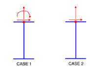
See below. Case 1 is from the original scheme from the OP where the guy wire was connected to a member sticking up above the roof. This results in applied loads in vert and horiz directions and an applied moment, all acting at the top of the beam. Case 2 is based on the detail shown by Tomfh, omit the applied moment due to where the force vector intersects the beam. In either case I think the horiz load/component wants to twist the beam. If there is a resisting element in line with the location of the horiz load (joist seat connection) than fine, that load can transfer to the joist top chord and to the diaphragm, otherwise it travels through the beam until it meets a resisting element imho.
1736134417020.png
 
The beam is horizontally restrained at the top flange so if the load enters there then there is no eccentricity and no resultant moment.
 
If there is a resisting element in line with the location of the horiz load (joist seat connection) than fine, that load can transfer to the joist top chord and to the diaphragm, otherwise it travels through the beam until it meets a resisting element imho.

As long as the top chord can span as a flat plate between resisting elements, there is no torsion. Which, in this case, should not be an issue as the load is only 8" away.
 
As long as the top chord can span as a flat plate between resisting elements, there is no torsion. Which, in this case, should not be an issue as the load is only 8" away.
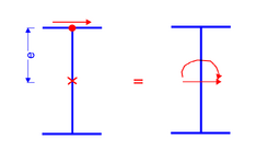
Capacity doesn't determine whether or not torsion exists, its just a moment about the longitudinal axis of the member induced by eccentricity of load.

The OP can decide if this effect is small enough to ignore or if the structure can handle the loads without issue.

1736175389687.png
 

Part and Inventory Search

Sponsor