Eng-Tips is the largest engineering community on the Internet

Intelligent Work Forums for Engineering Professionals

  • Congratulations waross on being selected by the Tek-Tips community for having the most helpful posts in the forums last week. Way to Go!

Retaining Wall - Active pressure with rock face within failure plane 2

Status
Not open for further replies.

danyul

Geotechnical
Jun 16, 2006
42
0
0
US
I have a solid basalt rock face and want to build a retaining wall in front of it... there will be soil placed between the wall and rock slope.

assuming the rock slope starts at the bottom-back of the wall and is steeper then the active wedge how do you calculate the active pressure? I assume it will be less than the full active wedge.

I know there are the charts for negative backfill but that is not the same thing correct?

Thanks
 
Replies continue below

Recommended for you

A drawing would help us more fully understand this question. Ultimatly, you'll have active earth pressure from the rock and also some active earth pressure from the soil backfill. It seems unlikely that you'd have sufficient width to develop full Rankine active earth pressure from the soil backfill. Just some component of the overall earth pressure. What do you know about secondary charactistics in the basalt (i.e., orientation of fracture planes and the like)?

f-d

¡papá gordo ain’t no madre flaca!
 
well i was assuming there wouldnt be any active pressure from the rock face... and i dont know the exact geometry yet. I was hoping there was a way to get the active force from the angle of the soil wedge between the rock and wall.
 
This isn't a simple question, even if the basalt is all bulletproof and would not contribute any active force (assuming that the cut is stable and wouldn't slide even without the wall). Depending on width of the space, and the type and compaction of backfill, I can see several different possibilities:

Arching could cause very large lateral forces.

OR

Compaction pressures on a stiff wall could cause very high lateral stresses, above Ko near the top of the wall. See, for example, Duncan, Williams, Sehn, and Seed in the ASCE JGE, December 1991, with errata in March 1992 (important), and discussion and closure in July 1993 (also important). This is based on placement and compaction of the fill in lifts, which imposes pressure higher than Ko at the top of the fill. If the horizontal dimension of the wedge of fill is small, it may not take very much deflection of the wall to allow enough horizontal strain that the pressure is much lower than with a rigid wall.

OR

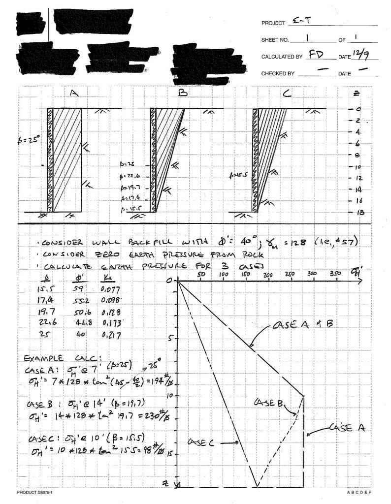
If the fill is not compacted much and/or the wall is flexible, you might be able to modify the Coulomb active pressure (based on sliding block) to account for the hypothetical sliding surface being steeper than 45+phi/2. Fattdad is, I believe, correct when he says you could not get the Rankine active condition (backfill material all at yield, with sigma1 vertical and sigma3 horizontal).


If it were me doing the design, I would start with the 2nd one, and see whether a reasonable reduction in the pressure makes a big difference in the design. Depending on height, length, and results of analysis, the cost difference to the client could be pretty minor, trading off hours you don't bill him for the additional study to nail down the loads better, versus the additional rebar. Or, the cost savings could be huge compared to the cost of your time to refine the analysis.

Could you compact the majority of the backfill well enough to control settlement, but leave a thin zone at the wall and abutment contacts that is not compacted as well, so the pressure is not so high after each lift is placed? EXCEPTION: If this wall forms the spillway chute for a dam, you need tight compaction against both sides, requiring wheel rolling, jumping jacks, pogo sticks, etc.

How's that for some vague and speculative advice?

Regards,
DRG
 
Just a suggestion, but you may want to consider backfilling the space between the rock face and the wall with stabilised sand or liquifill placed in lifts over a few days. I think this would largely remove the uncertainty of the pressures imposed by compaction.
 
say if we just poured gravel into the gap between the rock face and rock wall? is there a way to calc the active force based on the rock face and a known friction angle of the gravel?

we dont know the height of the wall or material but say 15 feet high made of stones and backfilled with some select gravel fill or clean gravel.
 
Richard Handy treated this case analytically in the ASCE Geotechnical Journal a few years ago.

Don't forget, that if water should saturate the backfill, the water pressure alone will probably be greater than the soil pressure you designed for. Water doesn't care how wide the space is.
 
To the question, "is there a way to calculate the earth pressure?" Sure. Let's say the wall backfill extends 2 ft behind the wall. Take a protractor and mark a line with a 45-(phi/2) measured from vertical. At some depth (likely around 3 ft or so), you will begin to intersect the vertical rock face. Calculate the active earth pressure at that depth and use that value for all depths below that depth - the earth pressure will remain unchanged. You just have to design the wall to hold up.

I know that this has come up in the last year somewhere. . .

f-d

¡papá gordo ain’t no madre flaca!
 
This has acatually been discussed in other threads - but my first step, I suppose, would be to treat it like pressures in a silo. One of the other threads linked to a paper on this. As for the rock contributing - if you just cut the rock, then I suppose there could still be some "expansion" due to the stress relief. If it is an "old" face, it is likely not unless there are joint sets that might be contributing to creep.
 
fattdad - i was figuring something like what you wrote... problem is that the rock wall will be built onto a rock ledge and the rock face behind the rock wall will be staring at the back of the wall at a steep angle. so the 45-(phi/2) is "into" the rock face at the start.

the height of backfill is about 18 feet and the width at the top is 5 feet... and zero at the base of the wall.
 
so the 45-(phi/2) is "into" the rock face at the start.

There is a Rankine wedge at any depth from the top also. Call that the start. If you are at a depth of 1 ft, you can strike off an angle for the Rankine wedge, just like you can at the depht of 2 ft.

Your problem is interesting as between the depths of 17.9 ft and 18.0 ft there is no soil (trivial) in the zone between the two lines for each of these Rankine wedges.

I bet you could think through how to handle that. If it was my problem, I believe I could work up something to account for your case. It seems like fundamental earth pressure stuff. (I'm not trying to make light of your question at all. It is a unique case, but I just seem to think after some pondering it'll become apparent how to handle the problem. Work up a sketch, make a pdf and post it to this forum. I'd be glad to look at what you've come up with.)

¡papá gordo ain’t no madre flaca!
 
fattdad - i see, thanks...

how bout this... this may be way off base but what if instead of using the phi angle in solving for the Ka, use the rock face angle from horizontal (a forced failure line).

 
You have described a potential failure surface (i.e., the rock face to aggregate backfill interface) that is a triangle with an 18 ft leg and a 5 ft leg. That triangle has two acute angles. Find the smallest angle and set that value to 45-(phi/2) and solve for "phi". That may more likely be the replicate angle to use for calculating a "Rankine-like" active earth pressure. I'd try it to see if you get a reasonable result.

f-d

¡papá gordo ain’t no madre flaca!
 
well... using different methods (note there is a batter on the inside of the wall of about 1H:13V and flat backfill)

Rankine- with a typical wedge using soil phi=40 the EFP = 29 pcf

with the potential failure surface with an angle of 16.5 between the inside face of the wall and rock face the new "phi" is 57 which equates to EFP = 12 pcf.

Coulomb- normal wedge EFP = 37 pcf

new "phi" EFP = 22 pcf

these seem "reasonable"...
 
Danyul - I sure wouldn't rely on that until you have checked the "silo" model (which involves arching), potential for hydrostatic pressure, and compaction pressures.

I heard what I thought was a tall tale when told to me by a farmer I worked for, but later reconsidered when I heard it from a geotech prof. It was about a tall, narrow bin full of corn, which blew out when the door was opened at the bottom and the corn arched across the bin, creating very large lateral pressures.

Aeoliantexan: Recall how far back Handy's paper was? I have the Journal going back to 1984 in my cabinet, but don't feel like plowing through the December indexes.

tan-1(18/5) = 74.5 degrees. 74.5=45+(59/2), and 59 seems a little high for an equivalent phi to apply to a modified Coulomb (not Rankine) wedge. (Rankine active assumes the whole soil mass is at failure, with sigma3 horizontal and sigma1 vertical.)

 
for review and comment:

earth_pressure.jpg


f-d

¡papá gordo ain’t no madre flaca!
 
fattdad
if im reading this right, and id like to think that i am...

case b would be the most accurate for my situation... not taking arching into account.

thanks
 
I think I'd evaluate the earth pressures using case B. I think the earlier idea of using the rock-slope angle and back-calculating some equivalent phi is shown to be incorrect by the sketch.

I think case B does take "arching" into account as the earth pressures actually decrease below the depth of 10 ft. To my way of thinking this frictional response is fundamental to the concept of arching (i.e., not acting as a hydrostatic force).

Interesting problem and it was fun to noodle through what I might do if the problem was mine.

Good luck.

f-d

¡papá gordo ain’t no madre flaca!
 
Status
Not open for further replies.
Back
Top