Continue to Site

Eng-Tips is the largest engineering community on the Internet

Intelligent Work Forums for Engineering Professionals

  • Congratulations cowski on being selected by the Eng-Tips community for having the most helpful posts in the forums last week. Way to Go!

Retaining Wall Base Width

Status
Not open for further replies.

engtiper

Structural
May 8, 2018
3
Hi guys,

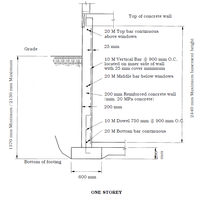
I am designing a retaining wall (2.7 m high) with toe only for the basement. The first floor is a timber floor so it is gonna be a cantilever retaining wall. As I have a look on the typical retaining wall detail. The width of base or rather footing is 2 meters with basement slab (concrete) sitting on top of it. So My question is, when I calculate the retaining wall, do I take 2 meters as the toe length or take the concrete slab into consideration? If i take 2 meters only, the overturning moment seems to be huge and it will fail.
Thanks
 
Replies continue below

Recommended for you

2 m. seems wide for a wall of that height. Have you taken into account the dead load of the structure to offset the overturning? (make sure it exists before they backfill).
Typically when I do these, the only issue is sliding (unless there is very little structure weight) which I use the slab to resist.
 
The weight of the slab that can be considered effective to resist overturning is limited by the bending capacity of the slab. You'll engage a significant portion of the slab as the wall rotation lifts it, until the slab cracks, then you have very little. It's not a configuration I would like.

Why can't the timber floor system provide restraint to the top of the wall? I'm a bridge guy myself, but I thought it was fairly common to have a floor system act as a horizontal diaphragm to brace the top of a basement wall. If the joists run parallel to the wall under consideration, some cross bracing or blocking may be required to engage a few of the interior joists to resist the moment from the force couple generated by the distance between the wall load and the resistance of the floor sheathing. I'm sure there typical details for residential construction that cover this.
 
You can take the slab/1st floor into consideration.....but follow the load path. If it's flexible enough (at some points) it may not provide the restraint you want. Usually a first guess size for a cantilever retaining wall footing is about 40-60% of the wall height.

 
I'm with Hotrod, why can't your timber floor provide restraint? That is how 95% of residential basement walls are done.
 
"Usually a first guess size for a cantilever retaining wall footing is about 40-60% of the wall height."

For a standard cantilever retaining wall, that usually works, but for a toe wall, without a heel for the weight of the backfill soil to resist overturning, the footing may need to be much larger. There needs to be significant axial loading on or near the stem, otherwise the moment arm needs to be very large, which means a wide footing.
 
"That is how 95% of residential basement walls are done."

Thanks for confirming that. I thought so, but I haven't looked at much building construction since my undergrad days in architectural design. We do anchored (tied-back) walls occasionally, but nothing with a diaphragm in front. Unrestrained toe walls are difficult to get to design. Where we can't excavate behind the stem location, we typically use a sheet pile or soldier pile wall.
 
I'm with Hotrod, why can't your timber floor provide restraint? That is how 95% of residential basement walls are done.

For a wall over 8' in height and a wood framed house? I'm not use to seeing that where I live. (Of course, you don't see many basements where I live either. [smile].)

 
9 or 10 ft basement walls here are the norm, treated wood sill plate with anchor bolts and the floor attached to the sill plate. Haven't yet seen a wall failure at the connection at the top, they're all due to lack of adequate vertical reinforcement resulting in horizontal cracking at mid-height. In fact our local amendments to the building code have this section for up to 8ft concrete walls (look how little reinforcement they let you get away with, I don't ever let this fly on my residential projects). For those that don't do metric, 10m = #3 20m = #6.
image_smvzow.png
 
That makes me a little queasy jayrod12. Seems like you'd have enough displacement in the top (due to diaphragm & shear wall deflection) where you'd be underestimating the needed steel in the wall. (If someone didn't have the top modeled as a spring support.)

I see similar set ups around here.....but that's for crawl space sized basements.
 
Thanks for all the replies.
I didn't take the timber floor as a restraint because there is a note saying backfill must be completed prior to construction of timber floor in the typical detail I have. (so to XR250, I didn't take the dead load of the structure into consideration). Also, the floor joists run parallel to the wall.
Do you guys treat the retaining wall (with timber floor) as simple supported like the pic that jayrod12 provide (with strip footing)? I don't quite understand how it is gonna work to be honest. I mean, what about the bar lapping at the connection of retaining wall to timber floor? Can anyone provide more details?
Thanks again.
 
Our notes indicate they can't backfill till the floor sheathing is in place, in your case we would design it as you've indicated.

Regarding connection at the top, it's typically just anchor bolts cast into the top of the wall through the sill plate. And when the joists run parallel to the wall, we just provide blocking in the first joist space or two or three depending on loading.
 
Do you guys treat the retaining wall (with timber floor) as simple supported like the pic that jayrod12 provide (with strip footing)? I don't quite understand how it is gonna work to be honest.

Me personally, I've always checked something like that with a variety of scenarios. It's essentially a propped cantilever....but I'd check it with a lateral spring at the top (i.e. the most flexible it could be) and a pinned (i.e. infinitely stiff in the lateral direction) support at the top with the at-rest pressure.

I'd also figure the rotational stiffness at the base. (I.e. I wouldn't run with it being perfectly fixed.)

All that should give you the max. moments (and their locations).
 
Sometimes you can't count on the overall stability of the structure (such as when there are open ended basement garages or when the structure is long and skinny) so designing as a retaining wall may be required.
 
XR250 makes a good point. There are other instances where the cantilever design methodology must be used.

In all fairness to the typical design detailing around here, we are in a super low seismic, I.e. we don't even bother checking because everything is wind governed. So our loading in that main floor diaphragm is fairly low.
 
jayrod12 said:
In all fairness to the typical design detailing around here, we are in a super low seismic, I.e. we don't even bother checking because everything is wind governed. So our loading in that main floor diaphragm is fairly low.

Same here, except I commonly have to design for basements that have 9 or 10 feet of backfill so overall stability of the structure or diaphragm strength comes into play.
I have seen a number of racked walk-out basement houses due to one side being mostly garage doors or windows.
 
I don't see how you're going to get the wall to design as a vertical cantilever with no axial load on the wall, no heel, and so little weight on the toe. This is the reason the typical construction sequence for a basement wall requires the floor sheathing to be in place to act as a horizontal diaphragm that provides resistance at the top of the wall.

Here are a few options I see:

1) Design the walls to span horizontally to the corners. This may not be feasible if the there are long runs between corners.

2) Shift the footing towards the outside of the wall so that there is a heel with soil weight on it. If you limit the equipment allowed to operate within the zone of influence outside of the wall to hand-operated equipment (plate compactor or jumping jack, no wheel loaders or rollers, etc.), you can consider only the soil pressure and keep the footing fairly narrow. If space outside the wall is limited, you can keep the toe longer to give your resisting soil load on the heel a longer moment arm. With common granular soil as backfill, a 1 meter heel and 1 meter toe would likely be more than adequate. That's just my educated guess. Obviously, you'd have to do the stability calcs, but I gave the approximation to help evaluate this option.

3) Change the construction sequence to have the floor with sheathing in place before backfilling and provide a connection between the floor system and the top of the wall sufficient for the horizontal thrust due to the soil load. This would allow you to reduce the footing size to what is required for the axial load to bear on the soil.

"Also, the floor joists run parallel to the wall."

I addressed this in my previous post: "If the joists run parallel to the wall under consideration, some cross bracing or blocking may be required to engage a few of the interior joists..." Others can likely elaborate as to how this is typically analyzed and detailed, or alternative methods used to provide support.
 
Thanks guys. Really helpful.
The reason why there is not heel is because the wall is near the boundary.
This is the first retaining wall that I design for the timber floor on top and I have no idea why the typical retaining details I have seen so far in Australia for timber floor on top is unpropped. (this might be an example: adbrimasonry.com.au/LiteratureRetrieve.aspx?ID=176630). I haven't seen a strip footing with timber floor retaining system so far.
 
"The reason why there is not heel is because the wall is near the boundary."

Is it possible to get a construction permit (or whatever the equivalent may be) to excavate outside the boundary?
 
The IRC has prescribed 8" reinforced masonry and concrete foundation walls up to 10ft high with 10 feet of soil load and restrained by the first floor framing. This means contractors can literally just pick the foundation wall out of a table and build it (no architect or engineer's seal necessary for residential projects where I live). It's a tried and true design. It's how every foundation is built in my area unless the diaphragm cannot handle the load. Plus, the way the load is distributed, the majority of the load goes to the footing. It doesn't take much to restrain the top.
 
Status
Not open for further replies.

Part and Inventory Search

Sponsor