Continue to Site

Eng-Tips is the largest engineering community on the Internet

Intelligent Work Forums for Engineering Professionals

  • Congratulations SSS148 on being selected by the Eng-Tips community for having the most helpful posts in the forums last week. Way to Go!

Retaining Wall Footings (For the Fourth!) - Fixed or Pinned Base

Status
Not open for further replies.

Guastavino

Structural
Jan 29, 2014
381
In honor of a fantastic previous thread: Link

So, I have modeled this condition. See attached RISA-3D file. So, I believe it shows that the footing WILL transfer moment to the soil, and quite easily. So, I will go back to the original question lion asked, and say, can we live with that, or should we adjust the design methods?

Backdrop:
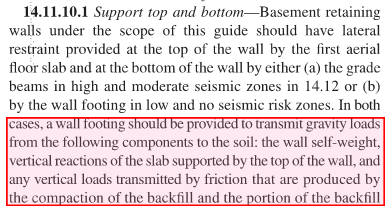
1. Pin-pin wall conditions for RESTRAINED retaining walls is conservative for the WALL rebar. No need to argue this.
2. Pin-pin wall conditions for RESTRAINED retaining walls is NOT conservative for the footings. The additional moment transfers to the footing and increases soil pressure.
3. Many in the previous thread assumed that soil spring stiffness, etc. was not that significant compared to stiffness of the footing/wall.
4. Respectfully, I challenge that assumption and present the attached model as evidence.
5. Intuitively, this also makes sense because to me, the stiffness of soil compared to a footing is still quite large.
6. I open the floor for debate as to what methods to use. It makes a HUGE difference in footing size, which means cost, and it may not have an advantage.

With that said, please no, "WELL, We've always done it that way and there haven't been problems" arguments. It's not that I don't care about that argument, it's just that I want to understand the behavior, not justify the design based on empirical experience (even though it has value).

Thanks to all and I hope for some great discussion.

ALSO, know that RISA-Foundation (Josh Plummer please feel free to comment!), does this method. IE, they transfer footing from the base into the soil and design the footing accordingly, leading to larger footings. Albeit, it doesn't model the soil springs, just assumes the moment transfers. The 3D model that is attached is a plate model has been created to simulate the soil springs.

 
 http://files.engineering.com/getfile.aspx?folder=088bd24c-5407-457f-b54f-7c8fb9d3241e&file=Test.r3d
Replies continue below

Recommended for you

Either assumption is valid as long as you properly detail your structure to accommodate them, at least in the ULS case. If you assume the wall is pinned to the footing, you correctly note this increases soil pressure. The soil will "fail", which really just means have unacceptable deformation, and you then have the pin-pin condition. If you assume pin-fix, and appropriately size the footing, then the soil resists the load.

Caveat - in my mind the first case may create serviceability issues, perhaps large soil movement, or large crack widths at the interface between wall and footing. I like the idea of considering it pin-fix. Then again I do industrial work so what do I know
 
Fun. Stat holidays were made for overthinking things. Here's my analysis of the things that could potentially go wrong by assuming a pin connection where, in reality, moment will develop.

1) Soil failure? Nope. For the very common case where bearing capacity is governed by settlement, I would argue that the addition of moment to the soil/footing interface would not really alter the average settlement strain beneath the wall.

2) Bending failure in the strip footing? Sure but who cares? I'd expect the footing to yield flexurally and then start to behave like the pin that we were hoping for in the first place.

3) Shear failure in the strip footing? Yeah, you might see some overload relative to the pin-pin case so that's probably legit.

4) Anchorage failure in the strip footing when the wall rebar tries to pull out under moment? That's probably legit too and a bit scary as that could compromise your flexural depth in the footing. One would hope that the axial force in the wall would prevent the moment in the joint from ever inducing significant tension. That's hard to guarantee of course.

I would submit that the modelling assumptions that led to the detailing below (not mine) probably represent a scarier issue.

Capture19_q5n99r.png


I like to debate structural engineering theory -- a lot. If I challenge you on something, know that I'm doing so because I respect your opinion enough to either change it or adopt it.
 
KootK,

Now that is a detail for the ages right there...If there was a such thing as a "structural ambulance chaser" lawyer, they should take stock in the company producing details like that...

Anyways, I think I'll likely split the difference by "allowing" a higher soil bearing pressure to develop based on the fixed end moments and designing the wall rebar for Pin-pin. This will help the footing during construction too when they start to backfill before the slab is placed.

I still think it's an interesting problem. I, like you (KootK), agree that the error in neglecting the moment transfer into the footing is potentially scary.

As an aside, and I don't mean this negative, but seriously is there an engineer on this site that could look at that retaining wall detail for more than 5 seconds and not question it? I am open to being the crazy one.
 
njlutzwe and KootK,
I agree that the section is unusual, but there may be reasons for some of the variations from what we consider as the norm. Perhaps a bit of discussion of specifics is in order.
 
njlutzwe,

I am no RISA expert, used it once, and still relatively new to the engineering field, but I had a few questions about your modeling.

It looks like you have a 4.23" thick footing, with a rigid element that is 6" long that is attached to to a piece of concrete 0.1" thick. You place the soil spring restraints on this 0.1" thick piece of concrete. Why do you not place the soil spring directly on the 4.23" thick footing? Were trying to capture some sort of soil behavior? If I were to model this I would have placed the spring directly against the 4.23" shell element.

Also, I noticed inconsistencies in your soil spring stiffness in certain spots. N754 has a stiffness of 1.563k/in while the typical stiffness is see is 1.823k/in at N893 for example. Was there a reason differing spring stiffness on the interior of the shell elements?
The edge springs seem to make sense with the value either being 1/4 or 1/2 of the total spring stiffness mentioned above.

Thanks,
S&T
 
I would argue, in part, that with the presence of a slab and a passive pressure against the footing, that there is a compensating moment resisting mechanism present to power any potential moment to the footing and underlying soil. The slab just needs to be present before backfilling for the mechanism to work.

After all, do we not rely on the presence of the slab to resist sliding, with the presence of this force creating a counter-moment potential?

Mike McCann, PE, SE (WA)


S&T

Different tributary areas result in different spring stiffness values.
 
njlutwze said:
I'll likely split the difference by "allowing" a higher soil bearing pressure to develop based on the fixed end moments

Please don't. After all we've been through, I feel as though I now have a vested interest in the success of your fledgling firm. I'd hate to see you reduce your competitiveness unnecessarily. I very much consider this to be one of those "do as the Romans do" situations given that, if you ignore the footing moment:

1) No code official will call you out on it.
2) No peer reviewer will call you out on it.
3) It'll be a bit cheaper to built.
4) It may be a bit cheaper to design.
5) I know you don't want to hear it but the very extensive history of success with the traditional method alleviates all practical concern in my opinion.

I didn't share that one detail because it was technically flawed. If anything, other than the turn of the hooks, it probably has more technical merit than what is typically done. The odd detailing results from considering the shear induced by the back-stay effect assuming both the footing and the SOG to be points of wall lateral restraint. It's pretty tough to argue with that really, especially for deep basements with shoring. And it will inevitably make for a wall shear problem and a demand for reinforcement. And you should never add that reinforcement if you hope to keep that sign outside your door illuminated.

For what it's worth, don't think that FEM has any place in routine foundation design. Other than, perhaps, outputting reactions and then designing the foundations just as we would by hand.

I like to debate structural engineering theory -- a lot. If I challenge you on something, know that I'm doing so because I respect your opinion enough to either change it or adopt it.
 
BadgerPE said:
Different tributary areas result in different spring stiffness values.

I caught that aspect, but node N754 and node N893 have the same tributary area. What explains the difference?
 
@sticks - N754 and N893 do have diff. areas. Not to the naked eye, but if you use F5 to measure it, you'll see a slight diff.

@kootK. As always, I appreciate the challenge. And it appears I misunderstood your OP, my apologies. With that said, it's clear that not all of the romans use that method anymore, IE RISA as one such example. I'm not saying that their method is 100% correct, but I could make a good argument it better captures the actual behavior of the wall/footing. So, with that said, do you (or anyone) know of any published references that cite your method of ignoring the lateral soil moment for the footing design? (I hope there are some because I do like that method, if I can find a way to justify it other than "as the romans do")

I don't want to over-design things. But, I also don't want to ignore frieze-blocking in wood structures just because over 99% of all wood buildings in my area don't have it. I see it as necessary, and I could make the argument for wall footings too.


Also in regards to that detail you posted:

1. Either the wall or the footing appear overdesigned or underdesigned, respectively.

2. Say you are relying on the SOG for sliding. OK, well that EJ material is going to get nice and squished and push any sealant out. That's all fine, and typically I ignore that effect, but this wall looks to be holding back quite a bit of load, more so than a typical basement retaining wall.

3. The hooks are turned the wrong way. This is a two-step problem. #1, it's an obvious mistake that appears not to have been found if that image is from a complete design. #2, if this easy-to-see mistake wasn't found, it begs the question, what BIG mistakes were overlooked? This is akin to when you talk to another engineer that uses the word "cement" instead of "concrete". If I hear "that cement footing" in a conversation with them, I don't need to hear another word, they aren't a qualified engineer. This isn't as bad, but that detail has blatant issues, the hooks being an obvious one, which would lead me to distrust everything else.

4. The detail shows confined rebar (the pier) in the wall, and yet the footing is that small?

Again, I'm not seeing the whole picture, but those are just a few musings based on what I can see.
 
njlutzwe,
Thanks for expanding on the questions you had about the section. Not my section, but I will make some guesses.

1. I would say the wall is designed primarily for bending. The footing in this case is probably just a starter for the wall forms, and I am guessing it is founded in competent rock.

2. I don't use joint filler in these situations, just turn up the plastic against the wall to provide some slippage parallel to the wall.

3. The hooks should turn in. Drafting error, should have been caught in check. I agree that errors like this send up red flags.

4. I didn't take those ties to be confinement reinforcement for a monolithic pier, but rather shear reinforcement for a wall of constant thickness. Maybe the detail 4 would clarify it. Footing, see 1 above.
 
If you don't consider the moment from the footing to the stem wall then I see the following issues:
- A crack opening on the soil side between the footing and wall. This is a serviceability issue.
- Exceeding the allowable bearing capacity of the soil at the toe of the footing. There are 2 thoughts here:
1. The potential for soil punching shear failure - not an issue since any local punching shear failure of the soil will release the moment imposed on the footing and redistribute the bearing stresses. Further, any minor rotation will actually increase the bearing area of the footing (3D element).
2. Local (lateral) soil shear failure - I would look to dismiss any thoughts on soil shear failure through the retained side since this shear plane, due to depth, should far exceed what was considered by the Geotech and acts directly against the retained soil. For the toe side shear, any slipping would relieve some of the soil stress at the toe and consequently relieve the moment imposed on the stem wall.

For simple basement type walls that are single story, I have no qualms with modeling the loads with a full pin-pin type analysis. I argue the crack problem away by detailing proper drainage at the base of the wall. Usually though, the retaining wall is not a simple single story retaining wall and I find myself using whatever methods I can to reduce or eliminate the significant lateral soil load from the structure's upper diaphragm(s). This includes looking at quasi-cantilevered to basement type options.
 
njlutzwe said:
With that said, it's clear that not all of the romans use that method anymore, IE RISA as one such example.

No way, no how am I willing to consider a software package "one of the Romans". Software developers are generally limited to presenting methods that are on the conservative / un-aggressive side. And that, for obvious liability reasons. Just look at the debacle we've gotten ourselves into with those "consider inflection points as bracing" check boxes.

njlutze said:
I'm not saying that their method is 100% correct, but I could make a good argument it better captures the actual behavior of the wall/footing.

Not so sure. I'd say that the lateral restraint / back-stay effect that informed the wonky detail that I posted is an even more plausible "accurate behavior" story. And if you try to pull that shear reinforcing business on any non-skyscraper building, you can expect a swift beating from your clients and contractors.

njlutze said:
So, with that said, do you (or anyone) know of any published references that cite your method of ignoring the lateral soil moment for the footing design? (I hope there are some because I do like that method, if I can find a way to justify it other than "as the romans do")

I'll try to sift through some of my home references over the weekend. I suspect that most references don't explicitly deal with this because the situation is thought simple enough that the design of the wall and the footing can be considered independently. For now, I'll propose this:

1) See the blurb from ACI314 below. It's not quite explicit in endorsing the pin-pin method but, in my opinion, is headed in the same direction.

2) Detailing varies but the most common version in practice seems to be interior face wall reinforcing and matching, interior face footing dowels. Exactly the opposite of what you'd do if you were wanting to transfer moment through the joint. I take that as evidence that the majority of Romans are doing pin-pin.

3) You rarely see top steel in the strip footings as you might expect if you were planning on transferring moment to the footing (non-eccentric footing). Again, I take this as an indicator of what the Romans have been up to.

Regarding your four questions on the wonky detail:

1) Hokie's response is correct.

2) It's less about whether you can rely on the SOG to take load but, rather, whether you can rely on the SOG NOT to take load when it would be undesirable for it to do so. Here, if the SOG takes load, then you set up the back-stay effect that I mentioned and create a monster shear demand between the SOG and the footing.

3) Since the wall is not designed to transfer moment to the footing, I don't see the hook direction as a serious mechanics problem. I just don't like it because it appears that there isn't physical space for the hooks and they're not shown at the bottom of the footing as I'd expect. Interestingly, this detail appears on a drawing stamped by one of the most famous living structural engineers out there. Seriously, like Fazlur Khan famous. You've read some of her papers and drooled over some of her projects, I guarantee it. Granted, the detail was surely created by one of her lackeys.

4) Hokie's response is correct.

Capture19_ewc6nx.png


I like to debate structural engineering theory -- a lot. If I challenge you on something, know that I'm doing so because I respect your opinion enough to either change it or adopt it.
 
Oh, and I would challenge you to produce an in-print example showing anything other than the pin-pin method for simple basement walls. Gotta show some Romans either way, right?

I like to debate structural engineering theory -- a lot. If I challenge you on something, know that I'm doing so because I respect your opinion enough to either change it or adopt it.
 
njlutzwe,

any response to:
S&T said:
It looks like you have a 4.23" thick footing, with a rigid element that is 6" long that is attached to to a piece of concrete 0.1" thick. You place the soil spring restraints on this 0.1" thick piece of concrete. Why do you not place the soil spring directly on the 4.23" thick footing? Were trying to capture some sort of soil behavior? If I were to model this I would have placed the spring directly against the 4.23" shell element.

I am genuinely intrested as to why you chose to model this in the manner that you did.

 
@KootK, thanks, unfortunately I don't have many good references for restrained retaining walls. If I run across one, I'll let you know. My "reference" was how RISA does it. You may slam RISA, but their engineers are quite good at what they do, and I have worked with them on various program questions and they document and think through things quite well. They aren't just programming it that way for no reason.

maybe Josh Plummer, RISA guy on this forum, can comment on why they do it that way?

@Sticks - reason for the 0.1" thick concrete is to model the thickness of the footing and transfer the horizontal load out at the BASE of the footing instead of the CENTROID of the footing. The reason it's thin is because I didn't want it to impact the vertical reactions much. Model likely isn't perfect, but I tried to get something accurate.

The reason for the 4.23" thickness was taking into account cracked section properties.

 
Nick said:
You may slam RISA, but their engineers are quite good at what they do

Whoa now cowbowy... I didn't slam RISA or their product in any way, shape, or form. I simply expressed my opinion that the methods presented in software and the methods used by practicing engineers are not always the same and, thus, I don't consider any software package to represent "a Roman" in the sense that we've been discussing it here. And I'd be quite surprised if Josh doesn't agree with me in this regard. Software automates calculation, it doesn't apply engineering judgement. Or at least it shouldn't. What we're talking about here is, decidedly, judgment in my opinion.

What are you trying to do to me? Get me kicked off of the RISA Christmas card mailing list?

I like to debate structural engineering theory -- a lot. If I challenge you on something, know that I'm doing so because I respect your opinion enough to either change it or adopt it.
 
Based on your previous posts, I was under the impression that you wanted to be convinced of the pin-pin approach. So, in an effort to help, that's how I've been tailoring my responses. If you're feeling attacked and would prefer to just be left to your own devices, let me know. It's not my goal here to needlessly hound you on your approach to basement wall design.

I like to debate structural engineering theory -- a lot. If I challenge you on something, know that I'm doing so because I respect your opinion enough to either change it or adopt it.
 
Status
Not open for further replies.

Part and Inventory Search

Sponsor