Eng-Tips is the largest engineering community on the Internet

Intelligent Work Forums for Engineering Professionals

Retaining Wall Pressure with Backfill Lense 1

Status
Not open for further replies.

Temporaryworks

Structural
Aug 27, 2017
46
0
0
GB
I am designing an anchored reinforced concrete retaining wall for a sloped backfill supporting a road. The slope has currently failed, our partner geotechnical company will be designing a temporary soil nail solution to enable us to safely install the retaining wall and anchors, which will then form the permanent support solution. Please refer to attached sketch.

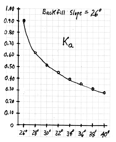
I have a query regarding how I could calculate the soil pressure against the wall. I have a lense of good quality backfill sat in front of some poor soil behind (top layer has friction angle = 26 and middle layer has friction angle = 28). Rankine theory doesn’t allow me to incorporate multiple layers of inclined soils, can you advise how I could calculate the wall pressure, incorporating the benefit of the superior soil backfill lense?

I could ignore the benefit of the backfill lense and just take 26 or 28 as my angle of friction and use rankine theory. I think that this may be very conservative as some of this backfill is set back quite far from the wall and the backfill lense in front of it with 40 degrees friction angle would definitely reduce the pressure on the wall. On the other side, if I took a angle of friction = 40 degrees, then this would neglect the poorer soil behind applying pressure.
Note: I have checked the slope stability of the soil as drawn and it is stable.
 
 https://files.engineering.com/getfile.aspx?folder=7638ce73-30e3-4c79-9b50-588bb4f8353a&file=Sketch.png
Replies continue below

Recommended for you

If your sketch is to scale, I think it would be reasonable to consider the granular backfill for the soil pressure. What I'm less sure of is how to account for the live load surcharge from traffic on the roadway. The conservative approach would be to calculate it using the native material it bears on. However, intuitively it doesn't seem like the wall would see much, if any, live load surcharge. Again, that's if the sketch is to scale.

With it being an anchored wall, you should be using the at-rest soil pressure coefficient.
 
You could assume, conservatively, that the 26 degree and 28 degree strata extend straight over to the wall. That will greatly simplify your design and probably not penalize the design too heavily.
Where do you intend to install the temporary sheeting wall? Will the temporary sheeting wall have its own tieback anchors?
You can analyze the traffic surcharge using a Boussinesq analysis. With the traffic so high above the top of wall and being so far from the wall, the traffic will not put much lateral surcharge load on the wall. Boussinesq analysis does not consider the soil properties.
I would use active earth pressure, not at-rest earth pressure, for this anchored wall.
How do you intend to install the lower tier of permanent tieback anchors with the shed building being so close (about 1.3 m off the face of wall) and its roof so high? What type of drill rig do you have that can drill the lower tier anchors in such a narrow space? In addition, you will probably need to use strand tieback tendons or, less desirable, very short lengths of bar tendons with many couplers and piecemeal sheathing for the unbonded length. Even using strand tendons, you could have trouble bending and inserting the strand anchor into the drill hole due to required sharp curvature encapsulated with less flexible double corrosion protection.
It might be worth considering installing a full-depth, temporary sheeting wall along the roadway gutter line and then excavate to install an MSE wall instead of an anchored RC retaining wall.

 
PEinc said:
I would use active earth pressure, not at-rest earth pressure, for this anchored wall.

I'm curious whether that's based on the assumed backfill method/condition or an assumed stretch/movement of the anchors. We would typically assume at-rest pressure for an tie-back anchored wall.
 
Temporaryworks said:
Rankine theory doesn’t allow me to incorporate multiple layers of inclined soils...

I would use one set of soil properties assumed to be equivalent to the combination of 26[sup]o[/sup], 28[sup]o[/sup] and 40[sup]o[/sup] friction angles... and this would not be just a wild guess:

1) Start by bounding the problem, both upper and lower bounds. That is, K[sub]a[/sub] at both 26[sup]o[/sup] and 40[sup]o[/sup].

2) Then determine values for several friction angles between 26[sup]o[/sup] and 40[sup]o[/sup].

3) Plot the results and see what what comes up:

Ka_Graph-400-1_xcchqn.png


From this graph, K[sub]a[/sub] is pretty sensitive to changes in friction angle between 26[sup]o[/sup] and, say, 32[sup]o[/sup]. From 32[sup]o[/sup] to 40[sup]o[/sup], not so much.

4) Using engineering judgement, I would assume an equivalent friction angle of 34[sup]o[/sup]... and that is is for worst case sloped backfill that extends an infinite distance horizontally... which is not the case. This is broken slope backfill, not as "bad".

5) For the assumed uniformly distributed surcharge loading from the carriageway, use the 2:1 slope soil loading assumption to "bring down" the elevation where this load is applied to the elevation of top of retaining wall:

fig_two_to_one-400_q7trxl.png


6) Then use the appropriate Boussinesq equation with calculated loading at top of wall elevation to come up with the carriageway's loading on the wall.

7) Add the results of Step 6 to results from Step 4 for total horizontal loading on the wall.
 
BridgeSmith, AASHTO's LRFD Bridge Design Specifications, Seventh Edition, 2014, Section 3.11.5.7 - Apparent Earth Pressure (AEP) for Anchored Walls, Page 3-117 shows use of Ka for deriving the AEP. This is for top-down wall construction (i.e., cut-walls). For non-gravity walls with compacted fill being placed behind (i.e., fill walls), there are other references for the developed earth pressure. If a wall needs significant compacted backfill, an anchored wall is not the best wall choice, especially if you also need temporary sheeting.
Tieback anchors are tested to a safety factor above their design load. Then they are locked off at about 75% of the design load. This lock-off load is generally around the theoretical lateral earth load. AASHTO's AEP has a built-in multiplier of 1.3 times the theoretical, triangular earth pressure. The reciprocal of 1.3 = 0.769 which is close enough to 75%. Therefore, there should be little to no additional elastic stretch in the tendons as the wall construction progresses (usually downward). If you are designing top-down, non-gravity, anchored walls for Ko, your walls are probably over-designed and over-cost by about 30% to maybe as high as 40%. Back in the "old days" (late 1970's to early 1980's), when tieback anchors were first being heavily proposed for permanent walls, there was much discussion about and a fair amount of design using Ko. However, as permanent tieback jobs were built, monitored, researched and became more common; it became clear that Ko was too conservative.

 
Thanks all for your replies, they have prompted constructive discussion between myself and my design Team and I appreciate you taking time to respond.

BridgeSmith/PEinc - thank you for highlighting the risks associated with compaction behind the anchored walls, I had a plan to detail lighter compaction directly adjacent to the structure or use self-compacting fill (i.e. single sized gravel) but then I probably should make sure that the chosen angle of friction is reduced to suit.

SlideRuleEra - I like your approach to calculating pressure on the wall. It balances taking a logical approach that I can defend to the checking engineer without unnecessary conservatism.

geotechguy1 - it is a very valid point and we are sort of doing this. The current SI (produced by Client) provides what we believe to be onerous soil parameters for some of the soils - we are looking to our geotech partner to help us improve them if appropriate.

I will let you know the result of the design when it is done!
 
BridgeSmith, where controlling structure movement is critical, such as a dam with tiedown anchors, the tiedown anchor lock-off load is usually higher than 75%, commonly 100% of the design load so that any possible elastic tendon stretch can me minimized or eliminated and the dam can stay in tight contact with its supporting soil or rock stratum.

 
Status
Not open for further replies.
Back
Top