Eng-Tips is the largest engineering community on the Internet

Intelligent Work Forums for Engineering Professionals

  • Congratulations waross on being selected by the Tek-Tips community for having the most helpful posts in the forums last week. Way to Go!

Reverse automatic pressure loss calculations for multiple fermentation tanks to gas upgrader

Status
Not open for further replies.

Minkjan

Chemical
Feb 20, 2024
5
0
0
NL
I am currently working on a project to calculate and finally build to get multiple fermentation tanks ( 10+)the biogas to 1 gas upgrader via piping to make greengas. This will be done under low pressure and I am now running into a particular problem. I am trying to make a standard fill-in sheet to quickly calculate what the pressure loss is and I have also figured out that the most convenient way is to calculate it back and thus start from the upgrader back to the fermentation tanks.
I currently use this formula ∆P pipeline=p1*(1-√(1-((λ L)/D ∑ζ)*(Z T p0 ρ0 vo^2)/(Z0 T0 P1^2))
I would like a pressure of 125 mbarg at the uprader and would like to use this forum module to calculate p1 and ΔP pipeline at the same time to make an automatic schedule and work back. Do you guys think this is possible and if I need to use some more formulas please let me know, thanks in advance.

In which:
Δp = Dynamic pressure difference [Pa]
p1 = Absolute pressure at the beginning of pipe section [Pa]
λ = Coefficient of resistance [m].
L = Length of pipe section [m]
D = Interior diameter of pipe section [m]
ζ = Specific resistance of fitting or appendage [-]
Z = Compressibility factor of gas at p and T [-]
T = Temperature of gas [K]
T0 = Normal temperature [273.15 K]
p0 = Normal pressure [101325 Pa]
ρ0 = Specific gravity at T0 and p0 [kg/m3]
v0 = Gas velocity p0 and T0 [m/s]
Z0 = Compressibility factor of gas at p0 and T0 [-]

This assumes that there are no tight bends, tees or narrows in the pipe section. Therefore, ζ = 0. Also, for λ, the following equation applies
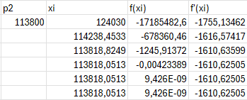
 
Replies continue below

Recommended for you

At low pressures, you can assume an ideal gas, no variation of gas density with pressure (compressibility =1.000) and typically laminar flow rates, so that can simplify your equations considerably.

Actually if you will always have such low pressures, I would make a table of capacities and pipe diameters and just select Diameter from the table. Get the friction loss/m and multiply by distance.

Colebrooke-White is used a lot for all pressures, high and low.

For your case a low pressure gas flow formula may be more convenient, such as Spitzglass.
Compare your calc with this one
Select your preferred equation.

If you are always in laminar flow friction factor is
Otherwise an iteration for friction factor does not usually require more than 3 tries.

It's also very convenient to check your low pressure work against the std chart

What's possible? Flow calculations always require that you know 2 of the 3 basic variables given a pipe diameter and length (both often assumed until you decide on something reasonable). Flow Rate, Upstream pressure, Downstream pressure. With any two, you can calculate the missing one.


--Einstein gave the same test to students every year. When asked why he would do something like that, "Because the answers had changed."
 
Hi,
Yes, this is possible. Iterative calculations. You need data about flowrate, the piping arrangement and pressure at one point (P1 or P2). If I understand well, your piping is long enough to be considered isothermal.

energy balance to solve :

∫ ρ*dP+G^2*ln( ρ1/ρ2 ) + (f*L/D+Σki)*G^2/2 = 0


after integration with T=cte

M/(Z*R*T)*(P2^2-P1^2)+2*G^2* Ln(P1/P2) +(f*L/D +Σki) *G^2=0 equation 1
or
F(P1)=0

with G expressed in Kg/s/M2 (mass flow divided by pipe section).
P1, P2 absolute pressure, M= molecular weight, f=darcy factor, L=pipe length, D=pipe diameter.

Use Newton Raphson to solve the equation in P1.
P1(n+1)=P1(n) -F(P1)/F'(P1)
Assume P1 value , knowing the others data, calculate P1(n+1),repeat the calculation until no variation between P1(n) and P1(n+1).

Have fun
Pierre

 
Thank you 1503-44 I will definitely check out the sites.

Pierreick, this is interesting to hear. With me indeed the flow rate, piping and p2 is known in this case 125 mbarg and want to automatically calculate back from there to see if it is a suitable piping and to see what blowers to put down at the farmers. I will look at the formula and let you know if I figure it out. You will be thanked
 
The mass flow method is fine, but very complex, given your low pressure requirements.

Try it both ways and you will see what I mean.


--Einstein gave the same test to students every year. When asked why he would do something like that, "Because the answers had changed."
 
Dear Pierreick,

I don't see the connection between the formulas and how to put them together and what to calculate with them. This is just me but could you explain this to me if you like?
 
Yeah. I mentioned they can be a bit complex.

Low Pressure
Your first post said mBar, but not important. 100kPag is still only 2x atmospheric, basically still nothing, especially for flow calculations. Anything under 150-200 psi is usually considered low pressure for flow calc purposes. Anything under 75 psig is low pressure for almost any purpose.


--Einstein gave the same test to students every year. When asked why he would do something like that, "Because the answers had changed."
 
Hi,
If you agreed with equation 1, integrated form of the energy balance, you obtain a function of P1 equal to zero.
The game is to solve the equation and find P1, knowing the other parameters (velocity or flowrate, density a T2, P2,T2,L,D,rugosity).
I proposed to use Newton Raphson method to find P1, n being the iteration.

F(P1) = A*(P2^2-P1^2)+B*ln(P1/P2)+C =0 with A= Mw/(Z*R*T); B=2*G^2; C =f*L/D*G^2 (in your case)
F'(P1)=B/P1-2*A*P1

Newton Raphson: P1(n+1)=P1(n) -F(P1(n))/F'(P1(n))

Perform calculation until P1(n+1)-P1(n) = 0
This is easy set on excel and the convergence will be very quick, less than 10 iterations.

Pierre
 
Pls note that many folk erroneously tend to neglect the pressure loss due to elbows. Include elbows and any other fittings and take into account whether elbows are SR or LR, since you are operating at very low pressures. Also check that piping is free draining, else condensate water will collect at low points.
 
Are the fermenters really going to operate at 100 kPag? This will make them pressure vessels and therefore very expensive. In my experience fermenters run at around 10 kPag.

Depending on the actual pressures, the situation could well be even simpler than suggested by 1503-44. They suggested that you assume ideal gas and laminar flow. If the pressure drop over the length of the pipe is around 10% of the upstream pressure then you can simplify further and assume incompressible (Darcy-Weisbach) flow with the fluid density taken as the average between upstream and downstream.

If you do find that you have laminar flow then you have grossly oversized your pipe. I don't recall ever seeing a gas pipe run in laminar flow.

George's comment on water removal is very important. The gas leaving the fermenter will be saturated with water and will likely cool down as it flows towards the gas processing plant. It is often difficult to make these lines self-draining and I have usually had to install automatic drains at the low points.

Katmar Software - AioFlo Pipe Hydraulics

"An undefined problem has an infinite number of solutions"
 
I did suggest that "At low pressures, you can assume an ideal gas, no variation of gas density with pressure , compressibility =1.000 and typically laminar flow rates, so that can simplify your equations considerably." He initially said "mbar" of pressure, not kbar, so I thought turbulent flow was not going to be even remotely possible.

And right, condensation will be a problem.

--Einstein gave the same test to students every year. When asked why he would do something like that, "Because the answers had changed."
 
Thanks everyone for the responses, I did not expect to get so many responses so quickly and it is appreciated.
Dear pierreick, I have been working on the Newton Raphson method and it is now in Excel. I am just not yet getting the values I expected or want. I may have entered the wrong unit for some numbers or entered them incorrectly.

T = Which temperature should be entered here? The absolute or the temperature in the piping?
M = Molecular weight in g/m or kg/m? and then should you use 16 g/m for biogas?
G = Here I did the mass flow kg/s divided by pipe surface m2

With the A,B and C I came up with the following numbers
A 0,007075
B 1032,245
C 29071,62

F = 0.007075*(113800^2-xi^2)+ 1032.245* ln(xi/113800)+29071.62
F' = 1032.245/xi - 2*0.007075 *xi

And see the picture as how it was done in Excel

Excel_2_kmxezo.png


Sorry to ask for help again, if you see what I did wrong I would love to hear it. Thanks in advance.
 
Biogas Density may is higher than methane, being 40% to 75% methane MW 16, with most of the balance CO2. MW 44, however there is also water vapor present in that balance.

--Einstein gave the same test to students every year. When asked why he would do something like that, "Because the answers had changed."
 
There is also a simplified version of the expression for compressible flow in Perry which is good enough for most purposes where line velocity is not high. See eqn 6-114 in the chapter on Fluid Flow in Perry 7th edn. You can ignore the log term in this expression for this approximation.
 
hi,
Seems OK to me. If you share your process data and piping arrangement I can have a deeper check.
You must initiate P1, P2 is a given data. P1 higher than P2.
As other said your Mw is a combination of CH4, H20 and Co2 at least. The temperature is the temperature of the product flowing in the pipe, in Kelvin.
I'm familiar with the SI system.
Note: BTW it's easy and more accurate to add the fittings and other valves to get a more accurate result.
Agree with Harvey, "I don't recall ever seeing a gas pipe run in laminar flow."

Good luck.

Pierre
 
I don't understand why you all are trying to use all these exotic equations for gas flow pressure drop. Why not just use typical equations like Darcy or Isothermal Gas Equation? Even Spitzglass I believe would yield similar results as the pressure is pretty low. Just start at upgrader at 125 mbarg and work backwards to the fermenters.
 
Well ... yeah. Katmar and I already suggested that, actually all of that, even Spitzglass, way up in post #1 to 5, even the link is to Oliphant, but apparently they're on a mission and won't be detured. My first boss told me that an engineer never calculates anything he doesn't have to, and when you do have to, never calculate more than you need to to get the answer good enough to answer the question. Computers have made calculations cheap and mother nature even knows she must comply with their results to 8 (in)significant figures. I'm not getting paid to argue about it....

Pierre, if you don't see laminar flow in digester design at minimum temperature, minimum flow, you probably never will.

--Einstein gave the same test to students every year. When asked why he would do something like that, "Because the answers had changed."
 
1503-44 said:
Pierre, if you don't see laminar flow in digester design at minimum temperature, minimum flow, you probably never will.

I suppose that under extreme conditions it is possible to get laminar flow, but that would not be the design condition. It's a bit like saying that if you close the valves completely there will be no flow.

I'm afraid this thread has gotten lost in the weeds. There are much more important considerations than how to calculate the pressure drop. Before looking at the pressure drop calculations I would want to know how many of the 10+ fermenters are running at once? What is the batch time? What is the gas generation profile over the batch? How are the fermenters spaced and located relative to the gas conditioner? What is the composition of the gas? Does it vary? What are the real pressures? Plenty to consider before we get into the detail of deciding on the calculation method.

Katmar Software - AioFlo Pipe Hydraulics

"An undefined problem has an infinite number of solutions"
 
Status
Not open for further replies.
Back
Top