Eng-Tips is the largest engineering community on the Internet

Intelligent Work Forums for Engineering Professionals

Reverse Flow HAZOP item 1

Status
Not open for further replies.

Shahin2020

Chemical
Jul 12, 2024
2
0
0
CA
Hi all,

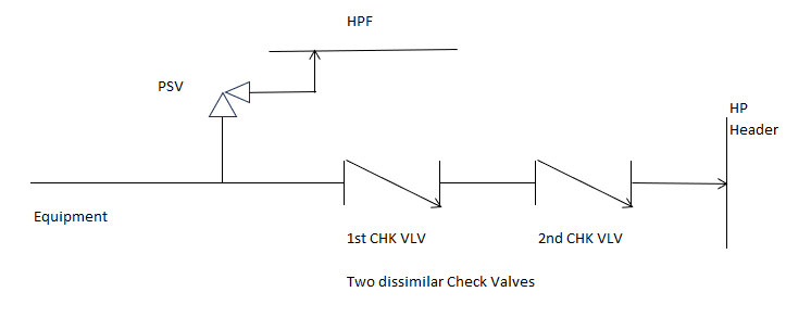
There is a HAZOP item to protect U/S equipment from a reverse flow coming from a high-pressure header.

There is a PSV D/S of equipment.
There are two dissimilar check valves to prevent the reverse flow.

In case of double jeopardy, when one of the check valves failed open, and the second one has leakage or failed open too the PSV will function to protect the equipment.

-Can we take advantage of each check valve port area as an orifice to drop pressure before functioning the PSV?
If yes,
-Is there any rule/API guidance specifically for sizing of check valves to ensure the PSV will fully protect the Equipment?

Thank you,
 
Replies continue below

Recommended for you

OP,
Is this HAZOP part of PSM? Because as soon as I hear double jeopardy cases being considered, it's giving me pause. Can you share a P&ID or sketch along with the controlling case causing the double jeopardy? What are your layers of protection? Are you considering double equipment malfunction as a controlling case?
 
I think the accepted flow is 10% area, so 2 is 1% of area.

Remember - More details = better answers
Also: If you get a response it's polite to respond to it.
 
I'm not aware of any HAZOP which considered check valves failing open. That's not a credible scenario in my view.

Remember - More details = better answers
Also: If you get a response it's polite to respond to it.
 
Are both or only one of these check valves tested and maintained every year ? Or neither ? Are they marked as safety critical check valves on the PID and Operating Manual? And included in the plant safety critical annual maintenance list ?

 
I was hoping OP would have come back on and provided more information but since this has been bugging me all weekend, I feel the need to put it in words.
My first though is concerning,
Can we take advantage of each check valve port area as an orifice to drop pressure before functioning the PSV?
Possibly, but it would depend on the type of check valve, possible failure modes and if the port areas would remain intact based on those failure modes. If you are unable to define these, then no.
Consider a ball check as an example. One failure mode could be a piece of debris getting lodged between the ball and the body, preventing it from closing. Another failure mode could be the ball retainer failing and the ball is carried off downstream. Two modes of failure but 2 different port areas for consideration.

My hang up is what OP is meaning by double jeopardy. What two abnormal conditions are being considered to be happening simultaneously?
Check valve one and check vale two failing?
Abnormal header pressure and both check valves failing?
Neither of these I would consider double jeopardy cases.

Here's what's been rumbling around in my brain.
If under normal operations the header pressure can exceed that of the design pressure of the equipment. Check valves should be assumed to be able to leak under normal operation. Then there should already be a system in place to handle that pressure and flow at the leak rates Littleinch indicated, to prevent overpressure of the equipment and PSV. The simplest system I would consider would be a FC valve between the equipment and checks. Since OP did not mention any device between the checks and the equipment, my concern is that the checks are being used to protect the equipment under normal operation. Which leads me to, why a HAZOP in the first place? Are they popping the PSV on the equipment because the checks have started to leak and are now considering validating the size of the PSV to handle that flow rate? Leading to, if we consider the check port area, we can use a smaller PSV? If this is the situation, I would be concerned that the HAZOP itself is making invalid assumptions on what a normal vs abnormal case is.

I may be totally off base here and I apologize to the OP if my assumptions were grossly incorrect but as I said, just had to get this out of my mind.
 
First and only log in last Friday...

I think DJ is one valve failing and the other passing. Failing is a bit vague...

Remember - More details = better answers
Also: If you get a response it's polite to respond to it.
 
-Is there any rule/API guidance specifically for sizing of check valves to ensure the PSV will fully protect the Equipment?
There is not. Each operator sets its own acceptable limits, e.g. see

ExxonMobil's std. 15C said:
6.14.2 Check Valve
A check valve is not effective for preventing overpressure by reverse flow from a high-pressure source. Experience shows substantial leakage through check valves. The following guidelines apply to the evaluation of reverse flow through check valves as a potential source of overpressure.
1. A pressure relief device is not required to protect piping against potential overpressure caused by reverse flow if the pressure of the high-pressure source does not exceed the short-term allowable overpressure for piping. The short term allowable overpressure for piping is 133% of the maximum continuous pressure for the specified flange rating at the flange operating temperature.
2. A pressure relief device is not required to protect a pressure vessel against potential overpressure caused by reverse flow if the pressure of the high-pressure source does not exceed the MAWP of the vessel.
3. For piping or pressure vessels not covered under 1 and 2 above, a pressure relief device may be required to protect against potential overpressure caused by reverse flow through a failed check valve. The following scenarios shall be considered

...

Number of Check Valves in Series 2 or more. Partial failure of one check valve.
Failed check valve behaves as a restriction orifice with a diameter equal to 1/3 the nominal diameter of the check valve. Each of the remaining check valves in series is assumed to behave as a restriction
orifice with a diameter equal to 1/10 the nominal diameter of the check valve.

Number of Check Valves in Series 2 or more. Total failure of one check valve.
Failed check valve is ignored. If only two check valves in series are installed, assume the second check valve fails partially open and calculate back flow assumed failed check valve behaves as a restriction orifice with a diameter equal to 1/3 the nominal diameter of the check valve. If more than two check valves in series are installed, assume that each of the remaining check valves behaves as a restriction orifice with a diameter equal to 1/10 of the nominal diameter of the check valve.

Chiyoda's std. LTC-PB-P0-004 said:
7.12 Check Valve Mal-operation
A check valve is not effective for preventing overpressure by reverse flow from a high-pressure source. Experience shows substantial leakage through check valves. The following guidelines apply to the evaluation of reverse flow through check valves as a potential source of overpressure.
1. A pressure relief device is not required to protect piping against potential overpressure caused by reverse flow if the pressure of the high-pressure source does not exceed the short-term allowable overpressure for piping. The short term allowable overpressure for piping is 133% of the maximum continuous pressure for the specified flange rating at the flange operating temperature.
2. A pressure relief device is not required to protect a pressure vessel against potential overpressure caused by reverse flow if the pressure of the high-pressure source does not exceed the MAWP of the vessel. With the explicit approval of the OWNER / PMC, on a case-by-case basis, a pressure relief device may not required if reverse flow from the high-pressure source does not exceed the maximum allowable accumulated pressure of the vessel.
3. For piping or pressure vessels not covered under 1 and 2 above, a pressure relief device may be required to protect against potential overpressure caused by reverse flow through a failed check valve. The following scenarios shall be considered

...

Number of Check Valves in Series 2 or more. Partial failure of one check valve.
Failed check valve behaves as a restriction orifice with a diameter equal to 1/3 the nominal diameter of the check valve. Each of the remaining check valves in series is assumed to behave as a restriction
orifice with a diameter equal to 1/10 the nominal diameter of the check valve.

Fluor's Flare System Process Design Manual said:
4.1.5.2 Check Valves
A single check valve is usually considered acceptable unless a potential exists for backflow of high pressure fluid to create pressure that exceed the test pressures of the equipment. In these cases, consideration should be given to the provision of a secondary device to minimize the potential for a reversal of flow. Sizing of pressure reducing (control or relief) facilities on the suction side of a pump to accommodate the peak flow following failure of a check valve is not normally recommended since reverse flow may destroy rotating equipment.

BP's std. GP 44-70 said:
6.6. Reverse flow
a. Overpressure resulting from reverse flow from a high pressure system shall be considered. No credit shall be taken for the presence of a single check valve or steam trap in a line. The following shall be considered:
1. Two check valves in series may be used as a means of overpressure protection, provided that the application and subsequent reliability and maintenance complies with GP 48-03. The installation of two check valves shall not be the sole means for isolation of low and high pressure sources. A positive means of isolation of the line shall be installed for maintenance.
2. Two dissimilar check valves in series used for overpressure protection shall only be used in clean, nonvibrating, nonpulsating services and shall be periodically maintained and tested to improve reliability by eliminating common mode valve failures.
3. If two check valves are used as a means of overpressure protection, their use shall be clearly documented in design, included in a register of safety critical equipment (e.g., the relief and overpressure dossier), and be subject to approval by the appropriate EA.
4. If the reliability of two check valves in series cannot be ensured, the reverse flow leakage rate shall be based on calculated flow through a single orifice with a flow area equal to 10% of the largest check valve flow area.
5. Orientation of check valves shall ensure that the check valves can function reliably in accordance with manufacturer recommendations.

JGC's std. 210-120-1-40 said:
6.4.2 Guideline for Overpressure Protection Conforming to API Philosophy
(1) Example Measures for Overpressure Protection
Any measures for overpressure protection shall conform to the project safety policy. Below are some examples of overpressure protection measures:
(a) To provide pressure relief device sized for reverse flow of gas stream from the high-pressure source:
The pressure relief device sized for reverse flow shall be regarded as mandatory requirement if no means of backflow prevention by automatic isolation is provided. Considering the required relieving rate and the number of pressure relief devices, the backflow-prevention device shall be either single check valve, or two or more check valves with dissimilar type in series. If the reverse flow through machinery causes loss of containment and this hazard is a matter of utmost concern, additional means of backflow prevention shall be provided.
...
(2) Estimation of Reverse Flow Rate
...
If the series of check valves with dissimilar type are provided, one valve is assumed to fail and the normal flow characteristics (with forward flow Cv) is assumed for its flow resistance. Other valve(s) are regarded to remain functioned to limit reverse flow. Unless the suitable leakage resistance is advised by vendor, the reverse flow through series check valves could be estimated as the flow through a orifice with a diameter equal to one-tenth of the largest check valve’s nominal flow diameter. Engineer shall determine the largest possible reverse flow considering any combination of failed and live check valve(s).
...

Worley's std. WS-DG-RP-007 said:
3.1.12 Check Valve Malfunction
A check valve may not be effective for preventing overpressure by reverse flow from a high pressure source. Experience shows that substantial leakage can occur through check valve. The following guidelines should be used to establish min requirements for protection of the low pressure side (more stringent guidelines may be applied on a case basis on consultion with the client).
...
Reverse flow should be estimated as follows:
(i) If one check valve is present, as a DESIGN CONTINGENCY (i.e. relief valve sizing cause), assume backflow equals 10% of forward flow. Where the normal flow is liquid (e.g. pump syste) but backflow may result in liquid followed by vapour, the vapour to an orifice with a diameter of 1/3 the valve diameter (i.e. approx 10% of a valve area). As a REMOTE CONTINGENCY (see below) assume check valve fails fully open.
(ii) Is two dissimilar check valves are present in series, the as a design contingency, assume one check valve rate. As a REMOTE CONTINGENCY assume the first check valve has failed completely and second leaks a rate based on 10% backflow.
 
I attached the Schematic

Hi @LittleInch Thank you for this guidance, this is exactly what I found in API 521 section 4.4.9.3.3 indicating all possible cases (as assumption) for a Reverse Flow Through Failed Check Valve:
1- The Failed Check Valve has No Flow Resistance in the Rev Flow Direction
2- The Failed Check Valve has the same flow resistance in the Rev Fl as in the Forward Fl direction
3- The Fld Check Vlv is equivalent to an Orifice equal to the check Vlv flow area without internals

This section also explains:
When multiple Chk Vlvs in series, assumed the smallest has completely Failed, all others have leakage, Two different practices are used to estimate the Rev Fl rate:
A- The Check Vlv as an orifice with a diameter of 10% of nominal Fl ID, (Orifice equal to 1% of Nominal Fl Area), so the Rev Flow is calculated using the Orfc area, then the Max Op P on the side normally D/S of the CHK VLV, and the allowable accumulation on the side normally U/S of the CHK VLV.
B- 10% of Normal Fl rate as the CHK valve as an orifice. The difference between the Max U/S and Max D/S pressure is used to estimate the orifice area. To calculate the Rev Fl Rate, the orifice is then rated using the relief fluid properties, and the allowable accumulation on the side normally of the chk vlv

Thank you @1503-44 it was helpful

New_Bitmap_image_lumqdl.png
 
Status
Not open for further replies.
Back
Top