Continue to Site

Eng-Tips is the largest engineering community on the Internet

Intelligent Work Forums for Engineering Professionals

  • Congratulations KootK on being selected by the Eng-Tips community for having the most helpful posts in the forums last week. Way to Go!

Review of a design 4

Status
Not open for further replies.

eli28

Aerospace
Oct 20, 2019
109
Hey,
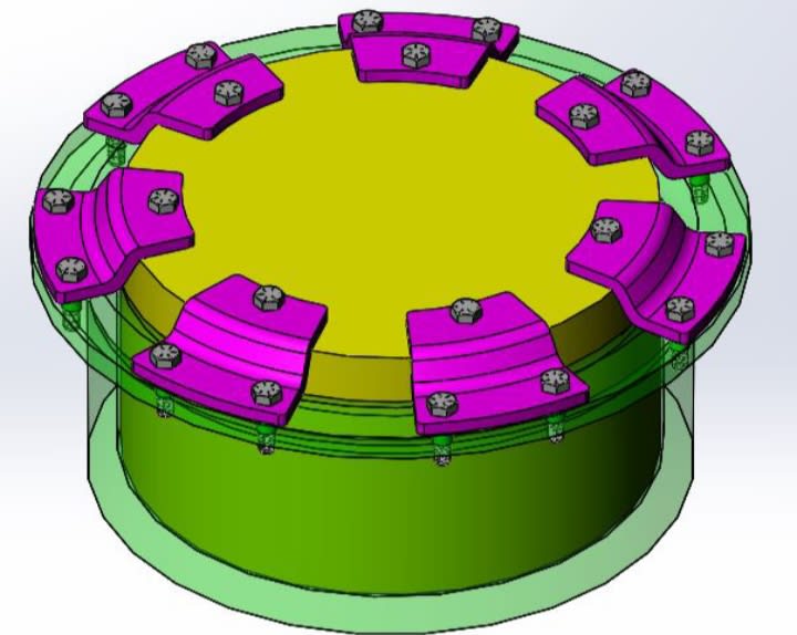
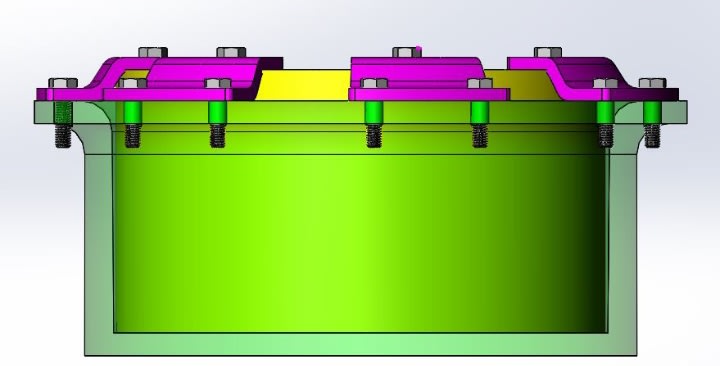
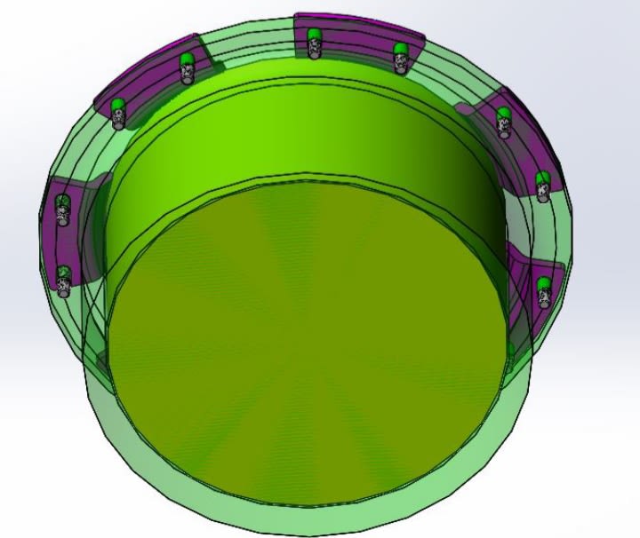
I am attaching pictures of a conceptual design.
The aim is holding the yellow inner part in place while the green outer part is held from its base and is subjected to accelerations and vibrations.
The aim of the purple parts is fixing the yellow part and minimizing (or avoiding) relative movement between it and the the green one.
If you ask why the purple part isn't a one piece the answer is an intention to save weight.
By the way, the radial clearance between the green and the yellow parts is 1 mm and it's filled with a cushioning silicon foam.
 
 https://files.engineering.com/getfile.aspx?folder=04515538-b9d0-41a6-b2cd-096e40cd7736&file=20210224_211013.jpg
Replies continue below

Recommended for you

Another picture
20210224_210959_icpp14.jpg

20210224_210947_ajnx8w.jpg

20210224_210935_tusn9s.jpg
 
If you see anything that isn't robust enough.
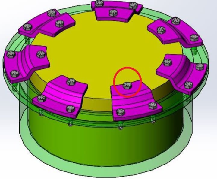
I was told that putting only one bolt in the indicated place in the picture below isn't enough because it may allow a relative rotation of the yellow and the purple parts. I am wondering if it's correct.
20210224_214414_khc9jl.jpg
 
No, since you have two bolts attaching purple to green.

Ted
 
it's not "ideal" but it probably is "adequate".

but we know next to nothing about this ...

how big are the bolts (probably #10 or 1/4) ?

how thick are the flanges ?

what material (probably some Al alloy) ?

what loads ?

what requirements (civil cert probably) ?

where (in a/c) ?

...

another day in paradise, or is paradise one day closer ?
 
I would rather talk about the principles of the design. I am sure there is an importance to every detail, but let's try to examine the concept.
 
How are the purple parts made? Compound-curve bend will require special tooling if it's formed metal.
 
Eli28:
Put a flange on the yellow part, and equally spaced bolts btwn. that flg. and the green part. That flg. might be about as thick as the pink clamp parts are, but this saves a bunch of bolts, much other work in manufacturing, and some more weight too. And, gives you a much more secure attachment, and makes things a little more water tight than the 1mm gap which you claim you have now. That is an overly complicated design for no apparent reason, except your CAD allows you to do it.

If you want to talk about design principles, it makes a hell of a difference in the design and detailing if you are talking about a 6” dia. object or a 6’ dia. object. And, if you don’t know and understand that engineering concept, and can’t explain your problem with enough engineering detail so real engineers can understand what you are trying to do, and maybe help you, you should go to a Uni to learn some basic engineering. Alternatively, talk with your boss about your design, so they know what you know and what you don’t know and they can guide you accordingly, to keep you and them out of trouble.
 
It's a lot of fasteners.

It will either push the yellow part down, or pull the yellow part up. Depending on a bunch of things. Which do you want to do?

It seems intolerant of tolerances.

Overall I think it is not a very good design.
 
Stars to all who point out the poorly defined OP problem.

"I was told that putting only one bolt in the indicated place in the picture below isn't enough because it may allow a relative rotation of the yellow and the purple parts."

Is the proposed "answer" to relative rotation to put an additional bolt in each inboard purple tab for a total of two?
If the second bolts on the scene and their clearance holes are precisely located like the original six, then I don't see 7 thru 12 limiting motion any more than 1 thru 6 did.

Asking bolts/screws to resist motion simply by "being there" is just rooky unreasonable in my opinion.
Even "fitted" bolts are likely to have only 2 or 3 players on the team that actually make contact with their fitted holes.
And then there is the effect of male threads in female threads. If the fasteners are loose, the clearance between the pitch diameters is measurable.
If tighter, where will the centerline of the fastener be ?
If the fasteners are reasonably tight, then the friction at the faying surface around each and very fastener makes a useful contribution.

Even much more mechanically secure dowels in reamed holes lose their minds when they are asked to deal with loads that vary in intensity or direction.
VW type 1 flywheel to crank attachment -

Even when fitted with twice as many 6 mm dowels, as in Porsche 356/912 engines, any deficiency in tightening the "gland nut" or faying surface irregularities or even operating abuse will leave the flywheel and crank to die a horrible protracted death.
 
Is this a part that has too fly? Or just sit on the ground? If it is supposed to fly its an ugly heavy looking thing.

By the way, you have posted a lot of very vague questions on these forums. We are not here to do your job; this is a forum for tips based on specific detailed questions.
 
Far too little information to offer advice moving forward.

The design has a lot of fasteners and I suspect this a) is not necessary, b) will cause frustration on the assembly floor due to torqueing sequencing and c) add cost to design & manufacture. If manufactured with clearance holes for fasteners and snug tight assembly, relative movement may be possible. It looks as though a clamping force is desired but doesn't appear this will be achieved. The yellow part may be pulled upwards.

Relative movement can be eliminated by direct mechanical connection such as yellow part with a flange as per dhengr's comments.

Indirect mechanical connection such as clamping to generate a friction force could help. Think over-centre clamp with a single fastener per clamp.
 
No one knows what the reason is for holding the yellow piece in position relative to the green piece. No one here knows which direction loads and torques are being applied in or the nature of any fluctuations or vibrations or impact loads or anything of the sort. BUT ... Be that as it may ...

The purple thing should be a single ring stamped out of sheet metal that can probably be thinner than what's already shown and thus lighter, and if that's not light enough you can probably cut lightening holes in it now that you don't need to worry about each triangle twisting relative to the others. And maybe you can cut down on the number of bolts (inner and outer) now that you don't need to worry about the triangle deforming or wiggling out of shape.

There's a vaguely similar loading condition that I can think of: the flex-plate that connects the crankshaft of an automotive engine (center 6 bolts and 2 dowels in the following example) to the torque converter of an automatic transmission (outer 6 bolts).
Note the lightening holes.
 
Agree we don't really understand the forces and I agree that it looks strange.

Why 7 fixings? And not 8 or 6 or 4?

An odd number evenly space still allows the yellow piece to be inserted in any orientaiton.

If the gap is 1mm and filled with some sort of foam then the available movement of the green to yellow piece is limited.

But each individual element becomes a stress concentration point.

I have difficulty believing a continuous thinner ring is heavier than 7 little clamps with 14 bolts.

Does the yellow thing sit on the base of the green hole or is it suspended by the clamps?

Remember - More details = better answers
Also: If you get a response it's polite to respond to it.
 
Hello everyone,

I am sorry for not providing enough information regarding my problem. You are definitely right that for a wise advice you need to consider every aspect of the problem, and what is clear to me shouldn't be for you.

I was sorry to read some of the itolerant responses, but on the other hand was happy to see some others that tried to help me be more focused.

I would rather end this controversial discussion for now, since I can't give you any new information.

Good night and thanks to those who kept being respectful.
 
Status
Not open for further replies.

Part and Inventory Search

Sponsor