Continue to Site

Eng-Tips is the largest engineering community on the Internet

Intelligent Work Forums for Engineering Professionals

  • Congratulations waross on being selected by the Eng-Tips community for having the most helpful posts in the forums last week. Way to Go!

Rewiring 120/240V motor to reverse rotation 2

Status
Not open for further replies.

moocowman1

Automotive
Dec 18, 2019
6
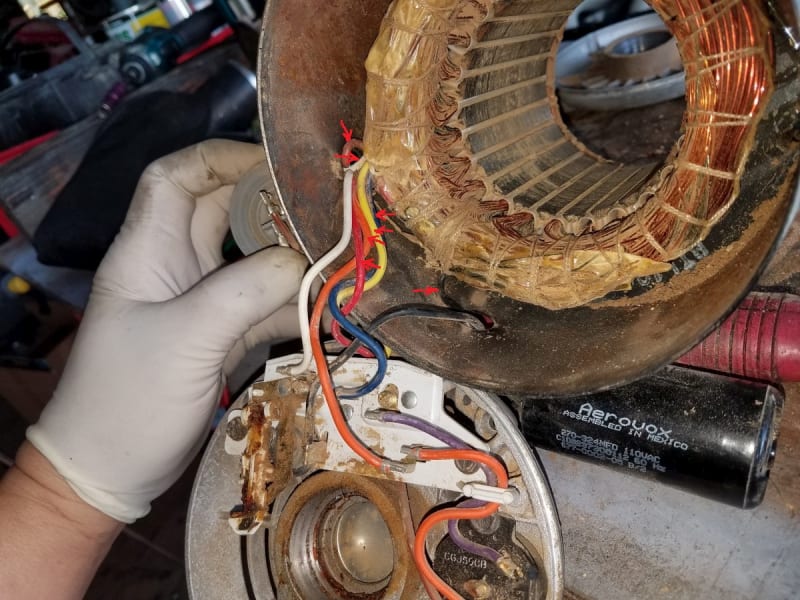
There are 7 wires coming out of the windings, indicated with red arrows in the attached pic. I assume the black wire on the right is one of the start winding wires. I need to swap that with the other start winding wire, correct? Could someone please let me know what other wire?
1_wz3dfz.jpg
2_tf6gpb.jpg
 
Replies continue below

Recommended for you

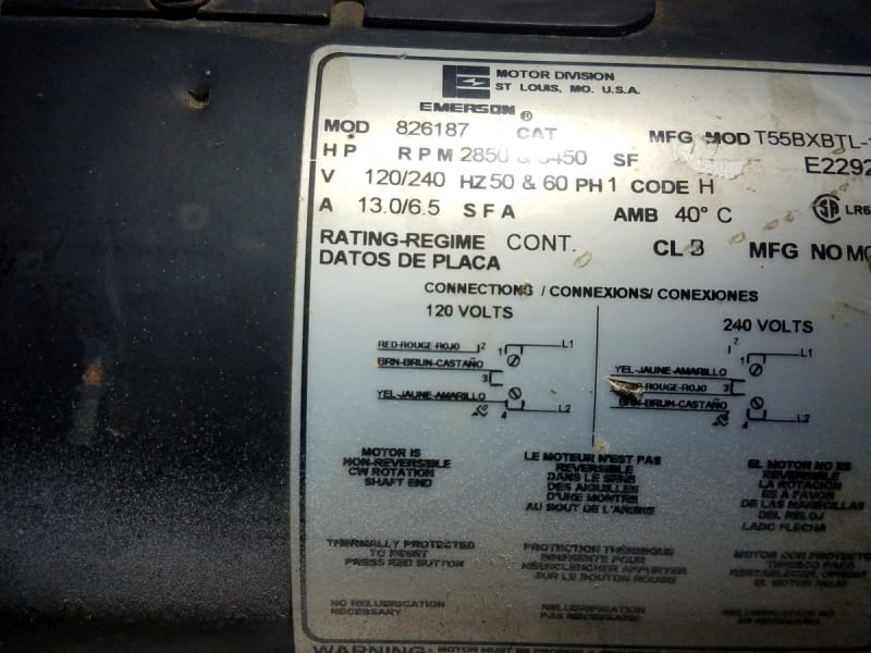
Did you happen to notice the statement on the label that it is not reversible?


" We are all here on earth to help others; what on earth the others are here for I don't know." -- W. H. Auden
 
In this case 'non-reversible' means that the common point between the start and run windings is not easily accessible. It is buried under the strings and wrappings. The start winding is the finer gauge wire. This is also a dual voltage motor so you really have to understand what you are doing to reverse it. It will involve cutting through the wrappings, cutting wires, and soldering new lead wires.
 
I think that I see six wires going to the terminal board.
1. White
2. Red
3. Blue
4. Black
5. Brown
6. Yellow
That are often two run windings with four leads and one start winding with two leads.
There is a black wire from the terminal board to the capacitor and one black wire from the capacitor to the windings.
Temporarily short the capacitor terminals together.
Look for continuity from the black wire on the terminal board to one other wire on the terminal board.
Check that these wires do not have continuity to any other wires.
Otherwise you have a problem and the motor is really non reversible.
If you have continuity from the black wire to one other wire only, interchanging these two wires should reverse the motor.

Replace all other wires on the proper terminals.
Remove the jumper across the capacitor terminals.

Bill
--------------------
"Why not the best?"
Jimmy Carter
 
Muthu; The lessor problems is extending the wires to the other end of the stator.
A possibly greater issue is that many of those type of enclosed motors have the stator closer to one end of the housing.
But, sometimes you get lucky.

Bill
--------------------
"Why not the best?"
Jimmy Carter
 
Edison123, I thought about rotating the stator. There is a gap through which I can extend and feed the wires. But as Waross guessed, the stator is in fact closer to one end and the windings aren't centered in the housing.

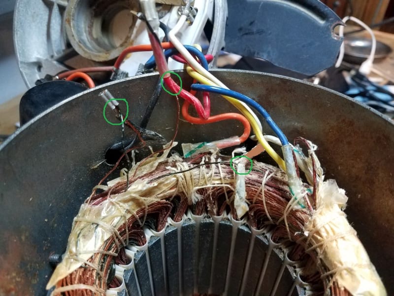
I've narrowed it down to 3 wires, black red and brown. I did some cutting to see what wires are connected to the small winding. The problem is there are 2 small windings, not just 1. One winding is copper colored and one is dark green. The black wire that goes to the start capacitor is connected to both windings. How do I know which of those is the start winding? Or are the both start windings because this is a 120/240V motor?

BTW, the remaining wires (blue, yellow, white and orange) were only connected to the large run windings.

3_cmibqj.jpg
 
If the red and brown wires are both connected to the same terminal then they are both start windings.

Bill
--------------------
"Why not the best?"
Jimmy Carter
 
Brown goes to the run capacitor. Red goes to the board, where it splits out to the orange wire and the thermal shutoff switch.
 
Do you think they're both run windings? If they are maybe I should swap them both?
 
There should be two start windings in a dual voltage motor. They are connected series or parallel for high or low voltage, just like the main windings.
 
There should be two start windings in a dual voltage motor.
VERY UNLIKELY.
The overwhelming majority of that size motor use a single start winding.
The start winding is in parallel with ONE of the run windings and thus always receives 120 Volts.
Why would there be two separate start windings?
X/R ratio and phase angle.
The high resistance of the start winding along with the capacitor helps develop the phase shift needed to develop starting torque.
If a winding is split into two parallel windings, each winding will have twice the resistance and 1/4 the inductance.
Inductance is roughly proportional to the square of the number of turns.
Put those windings in parallel and we are back to the same resistance and 1/2 the inductive reactance for a much better X/R relation ship for motor starting.


Bill
--------------------
"Why not the best?"
Jimmy Carter
 
A single phase, two pole, motor needs all the help that it can get to start.
A typical "Capacitor Start, Capacitor Run" motor uses two capacitors to start and one capacitor to run.
A smaller value of capacitor is used for running as is used for starting.
Rather than two capacitors, this motor may be using two start windings and one capacitor.
In that case, only one start winding would be switched by the centrifugal switch.
This would make it very problematic to reverse the starting winding.
But we are not done yet.
Identify one pair of run winding leads and reverse them.
Identify the second pair of run winding leads and reverse them.
Don't change the start winding connections.

Bill
--------------------
"Why not the best?"
Jimmy Carter
 
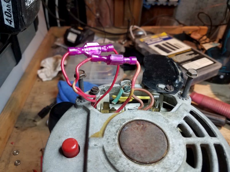
It works! I swapped the copper start winding wires and it reversed rotation. I extended the wires and added spade connectors in case I ever want to change rotation again. Thanks to all who contributed, Bill, Muthu and Compositepro. And to jraef, Mr. "..statement on the label...not reversible", you go on being a good little sheep and believe every label you read.

5_i0t2bp.jpg
 
Good that you sorted out the issue.
Not so good that you took that unnecessary potshot.
Remember, people here are giving away their valuable time and valued expertise for free.

Muthu
 
Status
Not open for further replies.

Part and Inventory Search

Sponsor