Continue to Site

Eng-Tips is the largest engineering community on the Internet

Intelligent Work Forums for Engineering Professionals

  • Congratulations waross on being selected by the Eng-Tips community for having the most helpful posts in the forums last week. Way to Go!

RHS Side Wall Capacity Check

Status
Not open for further replies.

Trenno

Structural
Feb 5, 2014
831
Hi all,

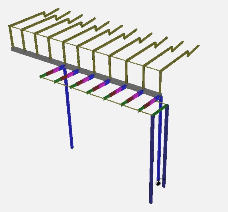
Currently going through the design of the glazed roof system, as shown below.

In particular, I'm having a good look at the connection of the cantilevered/tapered "T" member (multi-coloured 380BT) coming into the main beam(grey 400x300x8.0 RHS).

I would like to check the capacity of the RHS side wall if I were to directly weld the "T" member. Note I've used the plastic section modulus for the RHS side wall.

My design philosophy so far: Would be great if anybody could provide some feedback on my philosophy and/or ideas about this connection.
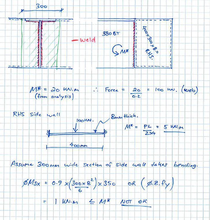
B_xhzamr.jpg


A_vc99yx.jpg
 
Replies continue below

Recommended for you

I believe that the method that you have proposed is reasonable and, as you are finding, probably rather conservative. The only change that I would suggest is that I would call the side wall pinned rather than fixed. There is some fixity, of course, but it will be partial and a pain to assess.

Most of the compression force will be concentrated close to the tip of the WT stem because the side wall will be stiffest there. As such, you're going to get a tension force very high on the RHS side wall and a compression force very low on the RHS sidewall. That should greatly reduce the flexural demand on the RHS side wall and simultaneously increase the local demands on your welds (unless you're claiming compression bearing at the stem tip).

There are a few documents that would be relevant here:

1) AISC design guide on HSS connections by Packer.
2) The CIDECT design guies.

To my knowledge, neither document covers exactly this case. However, they both cover similar cases and a review of the documents might generate some good ideas. This is a very common scenario. I imagine that everyone has their own take on it. Hopefully we see some of that show up in this thread.

I like to debate structural engineering theory -- a lot. If I challenge you on something, know that I'm doing so because I respect your opinion enough to either change it or adopt it.
 
Hmmmm, I suppose it comes back to the good old engineering judgement.

I understand where you are coming from regarding the tens/comp forces will tend towards the RHS return sidewalls.

If the sidewalls are pinned however, it also increases the flexural demand on the plate element in question...

Would a reasonable solution be to weld the T section to say a 16mm plate, which is then welded onto the side of the RHS?

Would be good to hear from anyone who has done a similar connection.

EDIT: Do you just register on the CIDECT website to download the PDF's which are "free of charge?"

 
Trenno said:
Would a reasonable solution be to weld the T section to say a 16mm plate, which is then welded onto the side of the RHS?

I wouldn't do this. The CHS wall shouldn't be the limiting factor here. It should definitely be possible to make this work with a direct weld.

Trenno said:
Do you just register on the CIDECT website to download the PDF's which are "free of charge?"

It's been a while but I believe so.

I like to debate structural engineering theory -- a lot. If I challenge you on something, know that I'm doing so because I respect your opinion enough to either change it or adopt it.
 
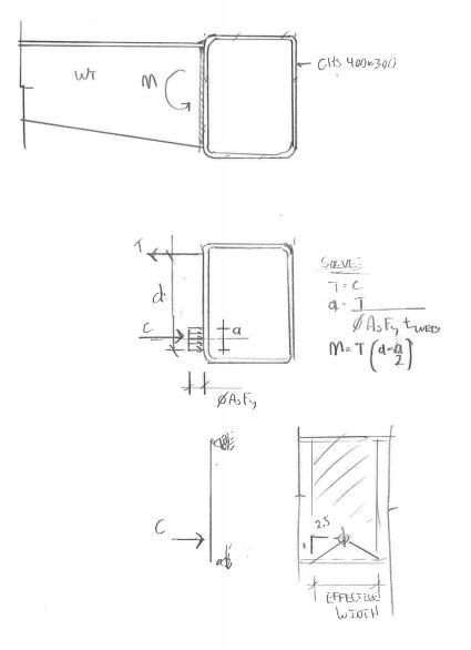
No doubt one could class this up with the right yield line model.

CAPTURE_muvkov.jpg


I like to debate structural engineering theory -- a lot. If I challenge you on something, know that I'm doing so because I respect your opinion enough to either change it or adopt it.
 
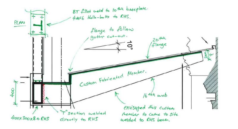
Thanks for the sketch, KootK. Throwing a spanner into the works here, but I forgot to add there is a nice cutout for the gutter in the T section.

All along I've assumed the bending stresses can 'follow' the flange around the cutout, as the section actually gets deeper than 400mm... How would one check this though?

Cantilever_T_Section-RHS_Connection_cmqdzp.jpg
 
I think you should consider bi-moment in RHS due to non-uniform torsion and warping effect.
 
Most definitely!^

That's why I'm going with a large and somewhat thick hollow section.

 
Trenno said:
All along I've assumed the bending stresses can 'follow' the flange around the cutout, as the section actually gets deeper than 400mm... How would one check this though?

Without introducing web stiffeners, it would be very difficult. You get cross flange bending and concentrated web loads at the flange knuckles. I would try to make it work using just the web section strength at the flange knuckle locations.

I like to debate structural engineering theory -- a lot. If I challenge you on something, know that I'm doing so because I respect your opinion enough to either change it or adopt it.
 
When I've done something similar in the past I've also checked the bearing on the RHS (especially at bottom flange). Your code probably has equations for bearing on hollow sections for a concentrated load acting over a bearing length, and for resultant combined stresses from bearing and bending in the RHS.

Some sort of check for the transverse and longitudinal stresses in the RHS is also warranted at the connection. At the top and bottom flanges the flange forces result in a tension/compression across the RHS flange that must be combined with the normal longitudinal bending stresses.

 
Status
Not open for further replies.

Part and Inventory Search

Sponsor