Continue to Site

Eng-Tips is the largest engineering community on the Internet

Intelligent Work Forums for Engineering Professionals

  • Congratulations pierreick on being selected by the Eng-Tips community for having the most helpful posts in the forums last week. Way to Go!

Rigid Diaphragm Analysis with Non-Orthogonal Walls

Status
Not open for further replies.

Celt83

Structural
Sep 4, 2007
2,070
Long shot but does anyone either know what the reference is or have a PDF copy of the reference on Enercalc's help page under the "Analysis Procedure" heading here: Link

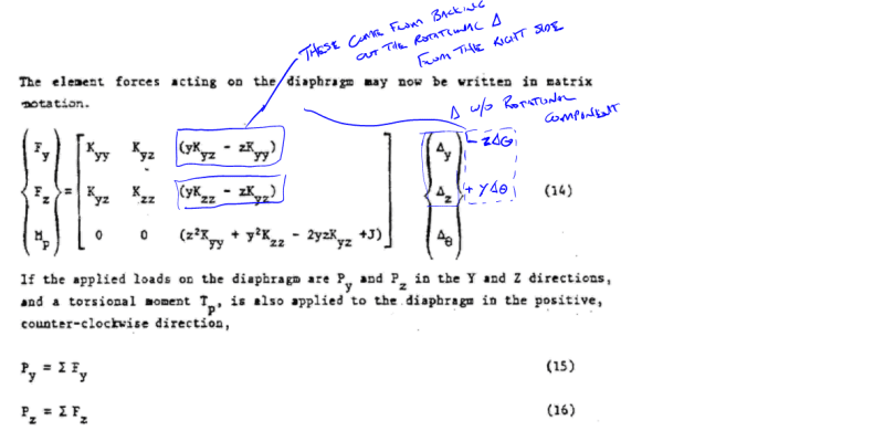
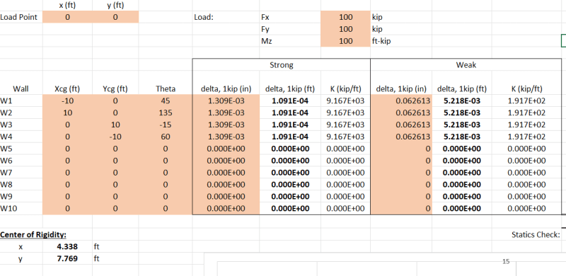
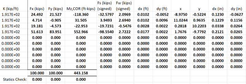
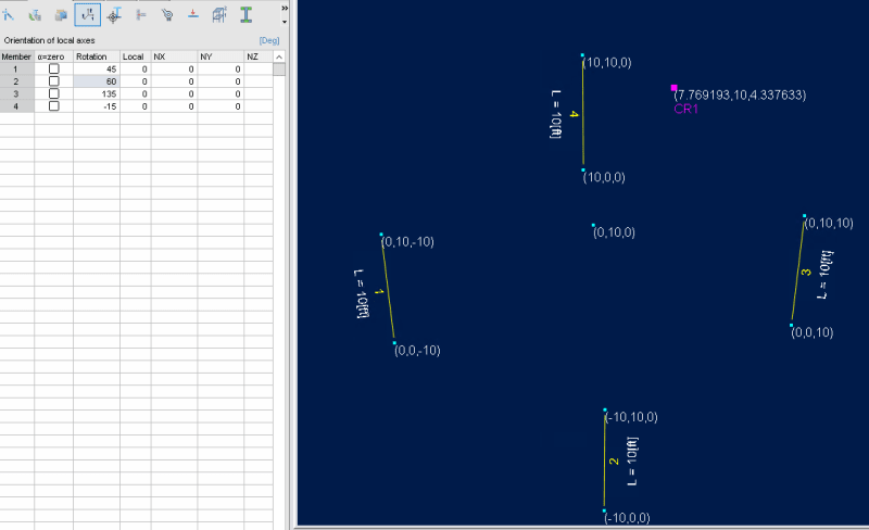
or alternatively know how to or have a good reference for assembling the global stiffness matrix for the system in the attached sketch:
Capture_fpqkd1.png


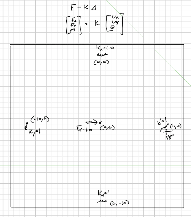
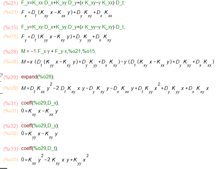
I'm getting tripped up with the formulation of the K's for the rotational degree of freedom.

I get the following for just the translational K's
[[1,0],[0,0]] + 2*[[0,0],[0,1]] + [[0.5,0.5],[0.5,0.5]] = [[1.5,0.5],[0.5,2.5]]

where the 0.5 K matrix comes from the transformation for the 45 degree spring using [[C^2,CS],[CS,S^2]] where C=Cosine and S=Sin which is a reduced form of the full transformation matrix.

From the linked reference that would lead me to:
[10,0,0] = [[1.5,0.5,Ktheta1],[0.5,2.5,Ktheta2],[0,0,Ktheta]].[Ux,Uy,Utheta]
I attempted using the Ktheta definitions from the link but I was not able to determine the J term in the lower right Ktheta term and applying what I did come up didn't result in any rotation for the system which, looks to be an issue with the last row which would take the form: 0 = 0 + 0 + Ktheta*Utheta which would seem always result in a Utheta=0?

My Personal Open Source Structural Applications:

Open Source Structural GitHub Group:
 
Replies continue below

Recommended for you

The K matrix should be symmetric so the two 0 terms for Dx and Dy in the Moment line should really be Ktheta1 and Ktheta2. Making this substitution I get approximately the same solution now but the difference is high enough that I don't feel as though I have it completely correct.

Spreadsheet attached with the test model data. Excel File


My Personal Open Source Structural Applications:

Open Source Structural GitHub Group:
 
Backup for the 0 terms in the M row needing to actually be the two Ktheta terms:
Taking moments about the datum point with positive moment being counter-clockwise
M = -Fx*y+Fy*x

Where Fx and Fy come from the first two rows where the rotational components of the deflection have been put back into the stiffness side of the function:
Capture_ajqbe7.png


Back substitution into the moment formula yields the following coefficients on the delta terms (x=y and y=z for comparison):
M_row_derivation_t4aqvg.png


Using this matrix arrangement removes the need for the J term in the moment which would need to be solved by reducing the Dx and Dy K terms to 0.

My Personal Open Source Structural Applications:

Open Source Structural GitHub Group:
 
to close the loop on this I corrected a few minor errors and worked out my own basis for the stiffness matrices and now have near exact agreement with a handful of software packages with the exception of Enercalc. It appears that Enercalc's rigid diaphragm tool may be mixing up it's own sign convention internally during the force recover stage as the results diverge rapidly from other well known software packages when angled walls are added into the mix. The Enercalc results can be off by 10’s to 100’s of kips.

A copy of the amended spreadsheet can be downloaded from here: Link

In the following images the Excel X,Y axis correspond the Software Z,X axis:
the test model consists of 10ft tall 60"x8" 4 ksi "columns" with fixed bases and free tops
All top nodes are assigned to a common rigid diaphragm in the software package
Applied loading is at coordinate (0,0) Fx=100 kips, Fy=100 kips and My = 100 ft-kips
Excel:
excel_lud2hq.png

excel_ixk95v.png

Software:
Center of Rigidity and Member Rotations (positive rotations are counter-clockwise as measured from the software Z axis or Excel X axis):
cr_geo_eayssr.png


Reactions (Excel Fx, Fy are forces applied to the diaphragm or -1*Reactions):
reactions_myujtg.png


Displacements (compare to the Dx(in), Dy(in) columns in excel):
displace_mheyzu.png


My Personal Open Source Structural Applications:

Open Source Structural GitHub Group:
 
Hi Celt,

Struggling a bit with what the intent is here. Taking a quick glance at the spreadsheet, it's a bit unclear what's going on in the sheet. Are you looking to develop both in-plane and out-of-plane forces on the segments that you have drawn on table in the Rigid Diaphragm tab?

How are you assigning wall stiffness/rigidity for in-plane and out-of-plane orientations on the walls? What is the composite material intended to be, can we perform distribution using other types of shear walls, or are you simply scaling off relative wall stiffness, and these forces then need to be analyzed wall by wall to to verify wall adequacy?

Are accidental eccentricity, amplification of accidental torsion, and load increases for extreme torsional irregularity accounted for in the analysis as it relates to seismic design?
 
Initial intent was verification of the force distribution reported by our software. The sheet in its current form reports lateral element in-plane and out-plane forces and global x,y displacement.

Wall/Lateral resisting element stiffness' are entered as in. displacement per 1 kip load in the strong and weak directions (ie analysis of strong and weak deflection under a 1 kip load needs to be done somewhere else currently). Values of 0 stiffness can be entered for either strong or weak axis as well. Design of each element would need to be done elsewhere also.

Automatic wind/seismic load application inclusive of accidental eccentricity is not done, the sheet is currently set up in a general sense where you tell it a single load vector and point of application.

It's current form is now a solid foundation, the stiffness matrix analysis and element force recover are consistent with more advanced software packages, upon which the various other automation routines for element stiffness and wind/seismic load application can be added via VBA routines, other on sheet calculations, etc.

My Personal Open Source Structural Applications:

Open Source Structural GitHub Group:
 
Hmm, interesting. When you say "global displacement", am I correct in assuming that is the relative displacement of the top of the wall to the bottom of the wall at each element, or is the displacement of the boundaries of the diaphragm? Does this global x,y displacement analyze for non-linear deflection performance of the lateral force resisting elements (ie a wood framed wall or diaphragm), or does it simply assume linear behavior of the lateral force resisting system?

Would be curious to see a version in something a bit more readable than excel cell code, do you have an open source project that this analysis is posted in? If so, what language?
 
Strictly linear in this application. The displacements indicated are per element centroid and are in the 2D plane of the diaphragm.

More or less boils down to F=Kd

K for each element is taken to be a 2D spring with i and j nodes occupying the same coordinate and the j node part of the rigid diaphragm.
Each spring is assumed to only have a strong and weak axis value such that the Kij = Kji terms are 0 for the elements local stiffness matrix.

Each elements stiffness matrix is transformed to the global x and y axis of the diaphragm by applying the formula:
TTKT = K'
where TT is the transpose of T and T is the standard rotation matrix found in most matrix structural analysis texts.

out of K' we only need the bottom right corner entries associated with the j node of the spring for the global stiffness matrix of the rigid diaphragm. This is because all i nodes of the springs have translation restrained so the partitioned form of the global matrix will have all unknown displacements associated with the rigid diaphragm.

To form the global K matrix for the rigid diaphragm:
All nodes are rigidly linked such that the direct x and y displacements are the same at every node so,

Fx = sum(K'11)dx + sum(K'12) dy
Fy = sum(K'12)dx + sum(K'22) dy

In addition to direct displacements the rigid diaphragm may twist, again because everything is rigidly connected everything experiences the same angle of twist.
The relative displacement of any node to the center of twist is:
xnew = Cos(theta)*X - Sin(theta)*Y
ynew = Sin(theta)*X + Cos(theta)*Y

assuming small values for theta, Cos(theta) = 1 and Sin(theta)=theta

xnew = X - theta*Y or dx = - theta*Y
ynew = theta*X + Y or dy = theta*X

**it is important to note here that X and Y are the relative values (signed distance) to the point of rotation

expanding further there are additional Fx and Fy forces generated from the rotation, found by substituting for dx and dy in the initial formulas:
Fx = sum(K'11*- theta*Y) + sum(K'12*theta*X) = theta (sum(-1*K'11*Y + K'12*X))
Fy = sum(K'12*- theta*Y) + sum(K'22*theta*X) = theta (sum(-1*K'12*Y + K'22*X))

The final Fx and Fy formulas are then:
Fx = sum(K'11)dx + sum(K'12) dy + theta (sum(-1*K'11*Y + K'12*X))
Fy = sum(K'12)dx + sum(K'22) dy + theta (sum(-1*K'12*Y + K'22*X))

the remaining statics formula is for the moment which I derived in an earlier post.

the final K matrix for the diaphragm becomes:
Fx = sum(K'11)________________________sum(K'12)_______________________( sum(-1*K'11*Y + K'12*X)) --- dx
Fy = sum(K'12)________________________sum(K'22)_______________________(sum(-1*K'12*Y + K'22*X)) --- dy
Mz = ( sum(-1*K'11*Y + K'12*X))__(sum(-1*K'12*Y + K'22*X))__(sum(K'11*Y^2+K'22*X^2-2*K'12*X*Y)) --- theta

*where X,Y are the signed distances from each element to the point where the static equations are being check about.

Edit:
Comparison with Autodesk Robot and the sheet using excels RAND() function to generate random coordinates for the lateral resisting elements and load application point. Get below a 1% difference for force and deflections, with one force outlier where absolute difference between the results is 0.002 kips. Wall stiffness for this run was calculated using the new CIP_Wall_Stiffness tab.
Capture_mpqv3l.jpg


My Personal Open Source Structural Applications:

Open Source Structural GitHub Group:
 
Status
Not open for further replies.

Part and Inventory Search

Sponsor