Eng-Tips is the largest engineering community on the Internet

Intelligent Work Forums for Engineering Professionals

Rigid Diaphragm for Two Story Garage

Status
Not open for further replies.

HDStructural

Structural
Apr 24, 2024
62
0
6
US
Hello All,

I am working on a two story garage with two garage doors on the front. The second floor has a few windows, but not much else for openings. I can't get the front walls to be IRC compliant at the first floor with either of their portal frame methods. I can get them 85% compliant with PFG and 95% compliant with PFH.

I am thinking that I will design the lateral system assuming a rigid diaphragm, which will put all of the shear in the back wall with some additional torsional shear on the side walls. This may also increase the diaphragm requirements above what IRC requires but I can take care of that. I am thinking that I will still use one of the methods above for the front walls which gives 85% to 95% of the required strength per the IRC for extra redundancy.

The diaphragm can be idealized as rigid per SDPWS section 4.2.5 based on shear wall and diaphragm deflection.

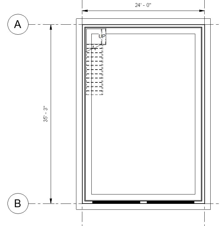
The building is not in a high seismic area, although it would still comply with the SDPWS rigid diaphragm requirements, L:W ratio less than 1.5:1, Length no more than 35' (less than 35' when looking at wall centerline to wall centerline). This gives me more peace of mind.

Screenshot_2024-08-27_085820_ddh4cx.jpg


What are your thoughts on this? Does this seem reasonable?
 
Replies continue below

Recommended for you

I'd say you're really stretching it with those measurements, but yes, it's within SDPWS. Looks like you have a length/width ratio closer to 1.67 because of the opening around the stairs. What are the wall heights and what are the applied plf loads? I'd be interested in doing a real quick check on this design assuming rigid diaphragm behavior.
 
When I run those numbers, assuming ~60plf load on end of cantilever at bottom of garage, I get an unblocked diaphragm performs fine on a strength basis, with design shear at 249plf along the top wall line, but with approximately 1.2in of diaphragm deflection at the bottom edge. Obviously if you intend to use portal frames, that deflection will be reduced significantly. This all assumes Doug Fir framing. Below is your distribution of shear in the diaphragm, with the '0' point as your upper wall.

HDStruct_dzpeab.png


Torsion along the N/S wall resolves to around 152plf in my analysis, but that includes accidental torsion factors which I forgot to turn off.
 
You could consider 12" strong walls outside the garage doors, which restrains the deflection to less than a quarter inch, reduces shear in the diaphragm, but induces more torsional effects.

HDStruct_1_urleoa.png
 
ChorasDen:
Is that a commercial piece of software generating those diagram or something you've created?

Why would adding the 12" shear panels adjacent to the garage doors create more torsion than the cantilevered option, wouldn't they end up moving the COR closer to the Center of Mass for a rectangular structure like this?
 
Celt, not commercial, it's a piece I wrote in C# about 3 years ago. I suppose I could make a public repo in github if there is interest in playing around with it from this community, let me know. Attached are the raw .pdf outputs of the the software, I'm in seismic country, and don't do much wind design, so the program is more geared for seismic design (automatically applies accidental torsion, and warns about allowable drifts and irregularities for seismic design).

Celt83 said:
Why would adding the 12" shear panels adjacent to the garage doors create more torsion than the cantilevered option, wouldn't they end up moving the COR closer to the Center of Mass for a rectangular structure like this?

The graphs (included in attached below) are a 2d representation, and only show the loading left-to-right. For a cantilever diaphragm, the center of rigidity is within the wall at the top of the structure, so no torsion is observed within that wall, as the center of rigidity passes through it. When we put strong-walls around the garage opening, it pulls the center of rigidity down towards the center of the structure (4.6ft as calculated). The center of rigidity is no longer along the top wall line, so now torsion is induced into that top wall line.

I use the 4-term deflection equations in SDPWS to equilibrate the stiffness of the supporting shear walls to determine the center of rigidity, and thus, the torsional effects.


Well that output looks fantastic compared to many of the options I've seen available.

I see the torsion now in the true cantilever state all of the torsion is picked up by the walls in the other direction, once the strong-walls get added now there are two brace lines in that direction to form a couple for the torsion so overall less torsion but now the wall in that direction experiences the impacts from that torsion.
 
Thanks folks, kind of you to say. It has some cool features, such as graphing locations where blocking is required within the diaphragm. You can see the blocking required in the first couple joist bays because total shear exceeds unblocked capacities. This is an example graph for illustrative purposes only and is not based on the information provided earlier in this thread.

HDStruct_2_ejmshz.png
 
If you don't mind sharing the code for your program I think there are a few of us here that would enjoy being able to peak at it on github.
 
Sure, let me go back and peak under the hood, it's been a while. It will take some time to get it into such a state that I would be comfortable posting it, so I won't have it up today or tomorrow.
 
As a tweak, any thought to forcing the blocking location to an increment of the truss spacing, say 2' or (or the 4x8 sheet size)? Or would you rather it as a decimal so you can see when it's 2.01 feet? And I don't quite follow those two graphs, as they change so substantially, did I miss an overhang or something?

Also, if you are doing deflection checks, the blocked/unblocked mixture (or a "mixed" diaphragm nailing, for that matter) isn't all that established in the code, if you ask me, but it has stiffness implications. Obviously seismic and deflection checks go together.

HD - late to the party here, but if you are doing an "open front" does the rigid diaphragm limitation actually apply for wind or is that specifically for seismic, I'm under the impression that the aspect ratio limit is for seismic alone.
 
Lex, I edited my last detail to indicate it's only for illustrative purposes. The tool itself does not take in the o.c. spacing of the joists, so it doesn't directly know how many bays that blocking will be required. Mathematically, it's only showing where blocking is needed based on the worst case capacity of the sheathing layout (worst case of Load Case #1 & #3 per SDPWS).
 
Status
Not open for further replies.
Back
Top