Continue to Site

Eng-Tips is the largest engineering community on the Internet

Intelligent Work Forums for Engineering Professionals

  • Congratulations SDETERS on being selected by the Eng-Tips community for having the most helpful posts in the forums last week. Way to Go!

Rolling - no increase in strip's length 1

Status
Not open for further replies.

polak7

Materials
Jan 23, 2015
54
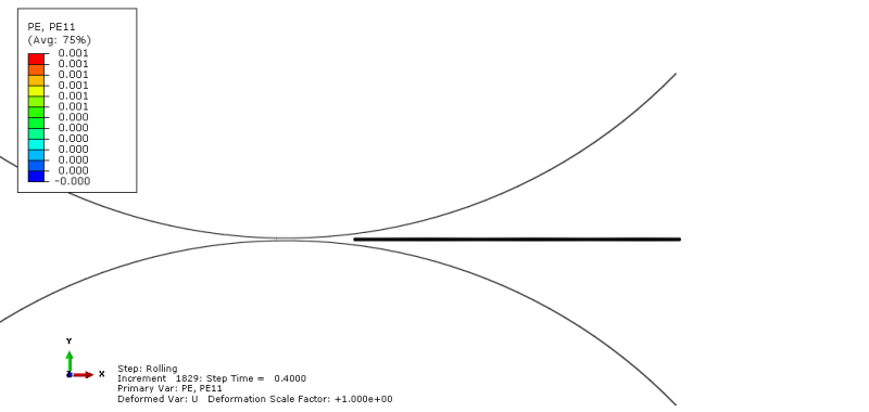
I have developed the rolling process in 2D.
The slab's geometry before the rolling was:
-length: 120 milimeters
-height: 2 milimeter

before_rolling_l6ny6v.png


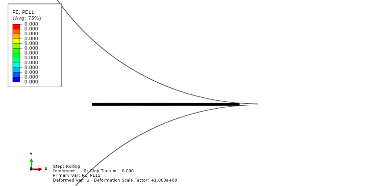
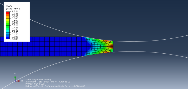
After the rolling process:
-length: 120 milimeters
-height: 0.9 milimeter

after_rolling_nlhwmr.png


Relative displacement in 1 direction: 8.82149e-005 milimeters

Why there is no increase in strip's length? It is very weird. I do not understand it. Some of the material disappeared, or what?
 
Replies continue below

Recommended for you

Yes, NLGEOM is on. This is plane stress (I have problems with plane strain).

I figured out where the problem is. The problem is with the slab speed application. This is the Temp-disp analysis, so the velocity can't be applicated in the predefined field. It has to be defined as a BC condition. Look at the figure:
velocity_nrm3h2.png


That way of velocity application (to whole slab) constrained any other move in X-direction, that is why there was no increase in length.

What is the best way to applicate the velocity to the slab in rolling process?
 
Initial velocity + Friction + Rotating velocity of the tools

Look at some examples from the Example Problems Manual.
 
You need generalized plane strain with temperatures so that the out of plane strain remains constant and not zero. For that you need to define a reference point and fix the two out of plane rotations to zero. Also apply the velocity to the front face so that the slab is pulled through.

 
Mustaine3,
The friction and rotating velocity is defined. I cant define the initial velocity through the predefined field. I can define the velocity through the BC, but it won't be "initial".

corus,
I changed section to Generalized plane strain. I changed element type to Generalized plane strain.
I defined the reference point and I applied the velocity to the front face. See the figure below:
1_jbfkar.png


I do not know how can I fix the two out of plane rotations to zero.
Anyway, without that fixing, the simulation crashes after short time and the error is: "Too many attempts made for this increment".
The moment of simulation crash have been shown in figure below:
3_rtdb3d.png


When I enter to the results module, the first what I see is the rotated image:
2_uek0nz.png

Is it due to lack of that fixation, which you were talking about?

I attach my input file, maybe it will be helpful.
 
Before looking at the inp file there are various ways of improving the model. Firstly you have symmetry through the horizontal axis so you only need half the slab thickness and one roll. Doing that you can, in effect, double the mesh density for the same number of elements. Secondly you have a uniform temperature throughout but you've used a coupled temperature displacement analysis. There's no need to apply a uniform temperature at all, unless you have temperature dependent properties, as that will just increase the overall size of the slab - which you might as well use from the outset. In addition there's no need to use a coupled temperature displacement model unless the temperatures depend on the displacements, say through contact for instance. You have no temperature variation, so there's no need. A coupled temperature displacement analysis just makes it longer for the job to run. Also for the element type I'd remove the reduced integration option as these elements tend to produce hour-glassing, contrary to what the manual says.
For this kind of analysis where you have contact and plasticity then it's better to use an explicit analysis rather than using standard as there are fewer constraints on achieving equilibrium everywhere. It should be possible to run it in standard though but it's a lot more trouble.

 
I forgot to mention that to restrain the reference point of the generalized plane strain element rotationally you have to edit the inp file manually. You can do it cae using the edit keywords feature. You'll have to check but I think it's freedoms 5 and 6.
I tried using symmetry and a finer mesh and running the job as a static, general model but didn't get the job to run much longer than you before it aborted due to too short a time step. An even finer mesh might help, but dynamic, explicit is probably the best option with the level of non-linearity in the model.
Here's a picture of the model I ran the just used half a slab and the top roll.

 
 http://files.engineering.com/getfile.aspx?folder=9d8a836c-65c5-47b7-abe4-ac4675ec9b72&file=rollingslab.png
corus - thank you for your help.

It seems to me, that I have to use a coupled temperature displacement model, because:
1) I have temperature dependent properties
2) I have temperature variation due to plastic work. Material deforms, then its temperature increases (it is applied by inelastic heat fraction)
3) There should exist the heat exchange between material and rolls (rolls temperature is a room temperature), but it does not work with roll defined as an analitical rigid body. Should I create roll as a deformable body with very big young's modulus (to simulate rigid body) in order to make heat exchenge possible?

The reference point is required only for applying restrains to it? Freedom 6 probably can by applied in Boundary Condition Manager. At least, if I type the displacement/rotation option and check the UR3, then in KEYWORDS I can see:

*Boundary
ReferencePoint_slab, 6, 6

So, I will add the freedom 5 to it.

The job started to abort after applying the generalized plane strain.
 
In other rolling models I've seen in the past, the rolls are modelled as rigid bodys, there is no heat transfer to the rolls (hence no coupled temperature displacement models), and strain rate dependent properties are used (which you don't have). In addition a dynamic explicit model is used. It may be that heat transfer to the rolls and ineleastic heating weren't considered as these are a highly local effect that were considered to have a negligible effect. If you were to try and use a coupled temperature displacement model to a solid roll then you'd have to consider gap conductivity to the rolls together with gap radiation as it made contact with the slab and also consider heat loss from the roll surface to the external ambient and heat loss from the surface of the slab. If the roll is water cooled then you'd have to know the heat transfer coefficient to the water. Given the highly local transient heat transfer at the contact point you'd also need a very fine mesh at the roll and slab surface to get any meaningful results. A lot of effort which may not be necessary. If you think that heat transfer to the roll is significant then take some measurements using a thermal camera (if one's available) to see if the surface temperatures change significantly during rolling. Otherwise take a simpler route to get the model running.

 
corus, thanks for your guidance.

My aim is to obtain the elongation of the material.
At the moment I run many of simulations with various parameters (different step, element type, speeds, etc.) to do that. There are also no coupled temperature displacement models. Additionaly in some cases I have turned off the material's speed BC and I positioned the material in such way, that it is in contact with the roll at the beginning. The roll should pull it.
Here is the screenshot from my excel sheet with my models description:
Przechwytywanie_nm7yxs.png


These simulations are running at the moment. The problem is that it takes a long time - a few hours in the best case.
I have noticed, that when initial thickness of the material was higher, the simulation takes minutes.

My material dimensions are as follow:
Length = 130 mm
Thickness = 2 mm (so it is 1 mm in model with Y-symmetry)

Roll diameter = 400 mm

Here is my assembly:
assembly_h4fcrr.png


I have a mesh consisting of 8320 elements. There is no reduce in simulation time, when I cut the number of elements below 1000.
Is there a way to speed up the simulation with such material thickness?
 
I used it. The simulation took about 4 hours.
After about 15 simulations with various parameters I realized, that only EXPLICIT with plane strain elements was succesful. I obtained the elongation. I think that if I do not apply the expansion coefficient to material, then I do not need the generalized plane strain elements (error appears when I apply them).
So, at the moment I will realize my target model and if some bugs appear, I will ask you for help.

Thanks, corus.
 
Status
Not open for further replies.

Part and Inventory Search

Sponsor