Continue to Site

Eng-Tips is the largest engineering community on the Internet

Intelligent Work Forums for Engineering Professionals

  • Congratulations KootK on being selected by the Eng-Tips community for having the most helpful posts in the forums last week. Way to Go!

Roof pitch on odd shaped building

Status
Not open for further replies.

SteelPE

Structural
Mar 9, 2006
2,747
I have an odd shaped building where I need to figure out the necessary pitch to the internal drainage system.

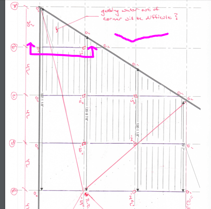
Normally I will give a top of joist elevation on my drawings and then give deviations from these elevations at the top of the column locations to help the fabricator with the design. However, I rarely work with odd shaped roofing systems. I am wondering how to figure roof pitch for such structures (see attached).

Normally I would figure roof pitch on the orthogonal axis (take the longest distance to the drain and multiply by .25 and then work from there). These are the red numbers shown on the attached drawing. This gives us some large initial pitches at B-2. One solution is to figure the maximum deviation at the drain than then work out the pitch linearly along line 2 (blue numbers). However, this option gives very little pitch from A-B.

On this project the client wants the perimeter steel all at the same elevation. The perimeter of the building is a load bearing wall system (think masonry). Joist run parallel to numbered lines (to allow for an easier bearing condition, girders run parallel to lettered lines.

Other options:
-Deviate the perimeter steel elevations (this would eliminate the issue, but make determining the top of steel elevation a pain). The client does not want to do this
-Eliminate the column at B-2 to "smooth" out the pitch with the roof members. This may cause other issues with members lengths during shipping.

Anyone have any thoughts?
 
 https://files.engineering.com/getfile.aspx?folder=9cb0311a-9102-4563-b71d-8e4997217fa9&file=img304.pdf
Replies continue below

Recommended for you

What is the issue?
How does eliminating a column change anything about roof planes?
I am guessing there is some significant assumption about construction that you aren't saying?
Are the elevation numbers measuring down from the perimeter top of joist elevation? If so, the blue numbers are making sense to me but the red numbers don't hit "0" elevation at the perimeter. I'm seeing a maximum distance of ~115'-120' along the line from C-3 to the drain (I'm not sure what this line is - it isn't where the valley should be). So the drain should be ~29" below the perimeter level.

I see 4 traiangular planes - why the focus on that one location (B-2)?

 
The red numbers are the roof pitch assuming 1/4 inch pitch per foot along the orthogonal axis from the furthest point. The blue numbers take the maximum pitch at the roof drain and take an even reduction of roof pitch back to the perimeter wall.

I am focusing on B-2 because we end up with 8” of pitch in approximately 10 feet (from B-2 to the perimeter wall).

Having longer roof members would make the pitch less dramatic, but cause other issues.
 
The red numbers indicate perimeter that is not level though.

The blue numbers indicate greater than 1/4" slope everywhere.

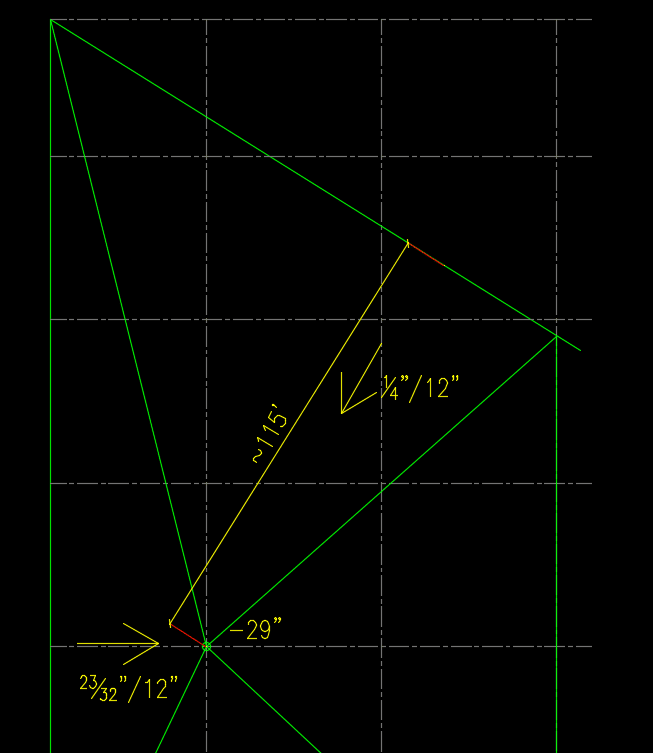
If you keep the perimeter level, the lowest acceptable slope would be from the farthest wall, perpendicular to the wall. The farthest wall would be the diagonal wall (assuming the cropped part at the bottom of the page is closer). Looks like that is ~115' away from the drain, and the close wall is 40' from the drain so the slope at that entire triangle at the plan-west wall would be 115/40 times the lowest slope. B-2 is in the low slope triangle.

Roof_slopes_rfh6tu.png


Aaron,

I never thought of looking at pitch being orthogonal from each wall. That’s an interesting thought. I have revised my sketch to your method. This time I am showing the framing on the plan so you have an idea on what we are trying to accomplish with the structure.

I am still concerned about how water at A-1 will make its way to the drain (especially considering all of these members have camber). Using your method the column elevation at B-2 would be 2” below the perimeter. That doesn’t leave much pitch to get the water from A-1 to the drain at E-2.

Would you think the sketch show is appropriate for roof drainage?
 
 https://files.engineering.com/getfile.aspx?folder=0c03c405-7bc2-4655-b6d6-f8ade7886df6&file=img307.pdf
I'm not experienced with large roofs like this - I work on residential mainly. But we often have some crazy roof designs and often the architect can't figure out the pitches, hips, and valleys so I end up telling them where everything has to be to line up. So I'm not sure what the standard is for framing "flat" roof pitches on large roofs - for small residential stuff I don't have to worry about internal drain with 1/4" slopes - just frame it flat.

What is the usual method to deal with valleys without a valley beam (since the girders and joists crossing valleys can't match both slopes - or can they provide two slopes along the top chord)? For example, this girder, even with a rectangular building, what would the typical method be? And what about the smaller framing members?

Girder_nbnrch.png


I don't see how getting water out of the corner would be a problem with minimum 1/4" slope everywhere.

 
I hear you in regards to residential roofs, those can be crazy.

In regards to getting the water out of A-1, the pitch from A-1 to E-2 is certainly less than 1/4"/ft.

In regards to large roofs, the roofs will tend to "roll down" as the joist change elevation. They do not fabricate open-web steel joists or joist girders in the profile you showed on your drawing (actually they can, but in 20 years I have never seen it done). I worked for a fabricator for a number of years and we have never had a problem because the decking is flexible enough to roll with the roof profile. I have attached a sample of a roof that is currently going into fabrication. As you can see, we don't typically do much other than not the deviation in elevation from the perimeter.

This project is throwing me for a loop. I have warned everyone that there may be consequences due to the odd shape, but nobody has listened. I like your idea of pulling from the far wall in a perpendicular direction...... to that extent, I can even pull from a fake wall perpendicular to the skewed wall (that dimensions ends up at roughly 120'... so slightly larger). I am thinking using this method is nothing different than getting the water from A-6 to the drain at B-4 on the attached file.

I also want to be cautious about what I am offering everyone, I want to be helpful, but don't want to be responsible for any issues should they arise.

I am also a little surprised that no one else has chimed with an opinion here. I appreciate your insight.
 
 https://files.engineering.com/getfile.aspx?folder=40f305a4-3770-4dbf-bc74-efe1b99cefd3&file=Sample_Large_Roof.pdf
So, the red lines delineate 4 triangular sections that meet a common drain at E2? Why wouldn't you apply the 1/4"/ft rule at those lines?

It seems to me that the right panel is showing a slope parallel to the joists that intersects the kerf (not sure what it's called, but this is mostly a geometry/math problem) running from A1 to E2, but once the water hits that kerf , there isn't enough slope to drain the water down the kerf toward E2. Since that kerf is the longest run, it should have the least compliant slope (1/4"/ft), since that ensures that any other line to the roof edge will have a steeper slope than the minimum required.

TTFN (ta ta for now)
I can do absolutely anything. I'm an expert! faq731-376 forum1529 Entire Forum list
 
It just seems to me that you'd find the longest distance spot on the edge of the roof, relative to the drain and set that line to be the minimum slope; then, any other point at the edge will have a higher slope to the drain, assuming the edges are all at the same height. The longest run will only have about 80% of the required slope, otherwise.

TTFN (ta ta for now)
I can do absolutely anything. I'm an expert! faq731-376 forum1529 Entire Forum list
 
Using a few extra well positioned roof drains might simplify the problem and reduce exterior wall height at the same time, offsetting cost of the extra drains. The roof drain shown is responsible for a lot of roof.

BA
 
SteelPE:

It's not clear to me exactly what's going on here, but if the perimeter steel is all set the same elevation the roof will have several twisted planes. It might be easier to set all the steel at the same elevation and have the roofing contractor use shaped insulation to generate the required slopes.

Regards,

DB
 
Agree with BAretired. You don't have enough internal drains.

Keep the structure flat and let the slope be handled by tapered insulation or lightweight insulating concrete. Add more drains and it will keep the taper thickness under control. Make sure you specify overflow drains or overflow scuppers in the wall consistent with code requirements.
 
Status
Not open for further replies.

Part and Inventory Search

Sponsor