Continue to Site

Eng-Tips is the largest engineering community on the Internet

Intelligent Work Forums for Engineering Professionals

  • Congratulations GregLocock on being selected by the Eng-Tips community for having the most helpful posts in the forums last week. Way to Go!

Rotary frequency converters 1

Status
Not open for further replies.

electrolitic

Electrical
Dec 9, 2007
105
Recently I took notice of an old (50's) but still running electric equipment. Two MG sets, 20 MW each, (60 Hz Synchronous Motor driving a 50Hz Synchronous Generator). One of the sets has an special sliding cradle that permits the turning (+/- 20 degrees) of the complete SM stator (hidraulic cilinder does it) for generators paralleling purpose. A description or paper/book that explains the dynamics involved would be welcome. Thanks.
 
Replies continue below

Recommended for you

electrolitic
May be i am wrong but i thought i would put forward a possible explanation for this apparatus.

Thinking about it from first principles i would assume that it is to slightly increase or decrease the the apparent rpm of the rotating magnetic field for a moment to allow the 50hz gen sets to be synchronized.

Think about what happens when you have diesels driving gensets. The rpm are never exactly the same so the frequencies are slightly different but every so often the phase voltages , etc will overlap and be identical at which point you would close the paralleling breaker if you were doing manually and the two sets would now have identical speed , frequencies etc.

If you had two 60hz synchronous motors running how do you alter the speed if the gen sets they are driving are not in sync for some reason .The motor speed is locked to the 60hz supply and in the days before VFDs what could you do.

So my theory is that if the two gen sets were just slightly out of sink at the time of paralleling you would move the "cradle" back or forwards slightly to momentarily speed up or slow down the rotating magnetic field to reduce the likelihood of pull out of the SM. One would assume that these units must be relatively low RPM and the hydraulics fairly quick acting for this to be effective.


Regards
Ashtree
"Any water can be made potable if you filter it through enough money"
 
"We" got rid of ours several years ago...but I remember them well. The conversion was bilateral 60 Hz to 25 Hz, but the principles are the same. The 60 Hz machines were of twelve-pole-set configuration, and the 25 Hz ones of five-pole-set design, leading to an operating speed of 300 rpm.

As a synchronous AC machine is loaded it develops either an angle of advance when generating or a retardation angle when motoring. If the frequency changer is operating alone, this is of little moment; but as soon as FCs are paralleled, load sharing can become an issue unless the angular displacements of the individual machines are properly aligned.

Some of our FCs could be started only from the 60 Hz end, others only from the 25 Hz end, and some could be started from either side. You can readily grasp that any synchronous AC machine having two or more sets of poles per phase can successfully "lock in" with the system at more than one location, and therefore if the incoming machine is being paralleled with another, when excitation is built on the idle end and the synchroscope selector engaged, the needle will typically settle at one of a number of possible angular displacements, depending on which poles of the machine have locked in.

If the synchroscope needle was not at or near the twelve o'clock position, pole slipping was commonly employed to drop the machine back one pole at a time until it was. If the angle of displacement was not too severe, the synchronizing breaker could then be closed and the machines in parallel would immediately begin sharing the load...although not necessarily equally, which is where the stator shift comes in: by physically rotating the stator of the machine or machines so equipped it was possible to exactly compensate for any existing angular displacement on a machine not so equipped so that the latter could be synchronized at exactly 0° phase angle. Once the incoming FC was tied to both systems, the stator shift on the machine so equipped could be adjusted as needed to achieve any desired load sharing setting desired.

Some machines, once brought up to speed and synchronized to the 60 Hz side could, with excitation in service on both machines, be disconnected momentarily from the 60 Hz side, at which point the machine speed would begin to drift down, whereupon the set could be synchronized with the 25 Hz system. If the 'scope was not at or near twelve o'clock it would not take more than four pole slips to get it there.

Hope this helps.


CR

"As iron sharpens iron, so one person sharpens another." [Proverbs 27:17, NIV]
 
I remember reading a paper years ago about a conversion at an old steel mill. The mill had both 60 Hz service and 25 Hz service.
There was a large induction furnace operating at 25 Hz. The utility phased out the 25 Hz service but the mill wanted to keep the furnace in service. The mill had a good selection of spare synchronous machines, both 60 Hz and 25 Hz.
The problem with an MG set was that there were no machines large enough to supply the furnace.
The problem was solved by running two MG sets in parallel.
The issue of synchronizing was solved by fabricating a coupling with provision to advance or retard one shaft in relation to the other.
The machines were run up and pole slipping used to get close to synchronizing. The synchroscope was observed and then the machines were shut down. The coupling was adjusted and the machines run up and the synchroscope checked.
This procedure was repeated until the 'scope showed synchronism.
I understood that the machines could then be synchronized and share the load without further adjustment.
Thanks for the chance to share memories.

Bill
--------------------
"Why not the best?"
Jimmy Carter
 
Lots of them in Europe (or were)

Mainly naval dockyards and some shore installations. All NATO ships are 60Hz, for standardisation, so need 60Hz for shore power when docked in all those 50Hz countries.

10 pole synchronous generator, driving a 12 pole synchronous generator at 600rpm common speed without a gearbox. They look just like a pair of diesel driven generators coupled together.

Also some in 50/60Hz mixed frequency countries - Saudi Arabia and Mexico spring to mind.

Power up to 5MVA, but units were made down to about 500kVA

Some single running sets were without a rack. Generally, the larger multiple unit sets had racks.

The generator stator was supported not on feet, but on grooved rollers on the bedplate, with semi circular rails on each end of the stator, Resting on the rollers. A semicircular rack alongside one of the rails, with a motor driven screw allowed the stator to be rocked for synchronising and power control.

So the motor driven screw could be used to adjust the phase angle of the generator to match the 60Hz supply.

There are end stops on the rack to prevent the racking drive spinning the stator too far (remember the stator power and instrumentation supplies)

We had at least one spin round - I seem to remember they found the end stop bolts loose in the bedplate afterwards.......
 
Where you have more than one unit, one would need to be synchronous motor driving a synchronous generator. But to make things less complicated additional units would only need to be induction motor driving a synchronous generator, after all the conversion would be within the slip of the induction motor, and make the additional units more standard with usual equipment.

But this is an interesting topic.
 
Sorry true, you could drive with an induction motor, even one designed for low slip.

However, you do not get 60 Hz from 50 Hz.

I fought a major UK electrical company over this point, and swept the floor with them! Customer had specified a 50/60 Hz changer, and they had an induction motor (and not a synchronous induction motor) as the driver.
 
Yes it is one way. But rarely do you need both ways.

If you have one synchronous converter, and one of more induction units.

If you are connecting two grids, and induction to induction is possible, and would still be able to transfer power.

The issue is that typical applications involve one large grid, and a spot grid.
 
Kind of special using induction motors and generators for a specific frequency. Both the motor and the induction generator have slip frequencies that are load dependent.
You may be able to match different frequency grids at one power level. The slip frequencies would have to sum to the difference between the grid frequencies.
Generally an induction generator feeding a grid or in parallel with a fixed frequency must be driven above the synchronous speed. That is hard to do with a DOL induction motor.
An induction set would only work and play well in parallel with a synchronous set under special conditions.
Remember that with an induction generator the grid sets the frequency. The amount of over-speed and the attendant slip frequency determine the amount of load transfer.
The necessary parameters for efficient operation may be hard to achieve with a fixed ratio drive.
It may work BUT........

Bill
--------------------
"Why not the best?"
Jimmy Carter
 
Paralleling a synchronous/synchronous set with an induction/synchronous set would be an interesting task. You couldn't just use pairs of 12 to 10 pole machines or else the slip of the induction motor would keep the induction set from being loaded. You'd have to do something like pair a 60hz, 18 pole induction motor to a 50hz, 16 pole synchronous generator and use an induction motor designed to be at full load with 25rpm of slip. You also have to deal with the low speed induction motor having a low efficiency and terrible power factor.

 
But they do give you intertia, which electronics do not?

Btw the units with induction generators we made were single running - and from what I remember, only for industrial use, not for dockyards.
 
Historical anecdote / reminiscence:

Back in the day, some of "our" customers who had more 25 Hz loads they wanted us to supply than we had wires for [something which typically occurred at the time of frequency standardization, when portions of the system were being converted from 25 Hz to 60 Hz operation] and who didn't like the price we were going to charge them to bring the extra 25 Hz power to their site [since we would have had to either build additional lines for this express purpose or re-string the lines we already had] would get a [much cheaper in the long run] 60 Hz supplied 7 pole set induction motor of the appropriate rating and use it to drive a 3 pole set synchronous generator for some of their loads. We used to call this output "bastard" 25 Hz, since this type of FC's output power frequency would drop from ~25.7 Hz, inversely to the applied load. As a result when 25 Hz loads were being transferred between supplies it always had to be done on a break before make basis.

CR

"As iron sharpens iron, so one person sharpens another." [Proverbs 27:17, NIV]
 
Nice solution CR. That is very close to the frequency you could expect from an unloaded 25 Hz diesel generator with the standard 3% droop.
A no load frequency of 25.75 Hz. compared to your 25.7 Hz. Other than an occasional UPS that complained when it didn't see exactly 60 Hz, I never had a customer notice that the frequency of their standby generator ranged up to 61.8 Hz. Most of the sets that I spec'ed and installed were sized for starting A/C loads. Normally the sets ran at less than 50% load. Around 61 Hz was common and no-one ever noticed.
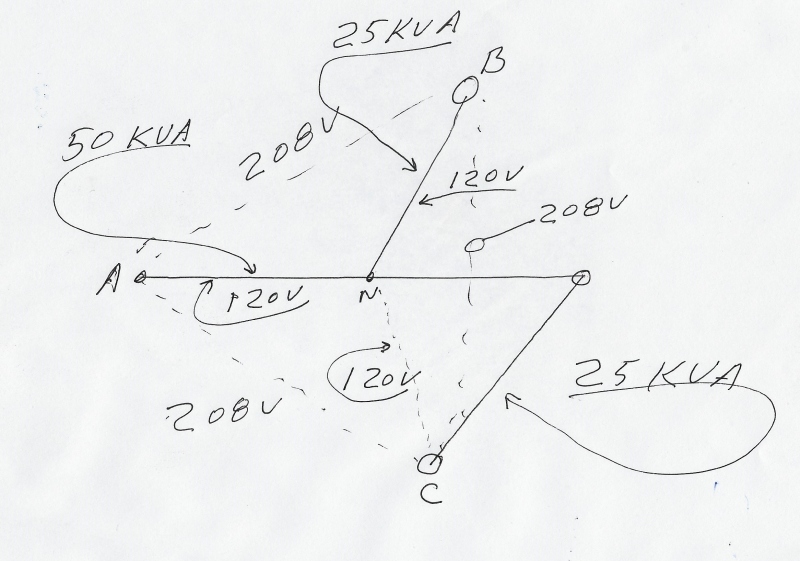
CR, while we are travelling down memory lane, Have you ever encountered a connection I heard called a "Winnipeg" connection?
This is a connection that uses two phases and the neutral, similar to an open delta connection to develop three phases from two phases and a neutral, BUT the output is 120:208 Volts.
Winnipeg_connection_x4ycwy.jpg


Bill
--------------------
"Why not the best?"
Jimmy Carter
 
Hoxton, The whole intertia issue is the problem that is developing with solar and wind energy today. And the problem is the rule makers in government don't understand.

Which makes a case for rotating capacitors to solve that and another voltage problem.

Have you heard this: "We can program the static inverters to simulate intertia"?
 
Winnipeg connection would be a waross question...I seem to have seen a post not long ago that referenced it...Eng-Tips search, maybe?

CR

"As iron sharpens iron, so one person sharpens another." [Proverbs 27:17, NIV]
 
cranky -
What is a "rotating capacitor"? Have not heard the term before. Overexcited synchronous motor?

ice

Harmless flakes working together can unleash an avalanche of destruction
 
To expand on David's answer;
Synchronous condenser; synchronous motor with no load and often with no shaft extension.
That removes the possibility that the mechanical department will attempt to add a mechanical load.

This also brings up a connection to the original issue of synchronizing equipment.
We were building a large mine mill. The 6 autogenous mills required 6000 HP each. The mills were about 30 feet in diameter with a ring gear around the circumference. A 3000 HP wound rotor motor was mounted on each side driving the same ring gear.
Had one motor been used it would probably been an oversized, overexcited synchronous motor to compensate for the KVARs consumed by the acres of flotation cells driven by 7.5 HP or 10 HP motors.
BUT, due to the load sharing and synchronizing issues with two synchronous motors driving the same gear, induction motors were chosen.
This left the issue of the KVARs consumed by the acres of integral HP motors plus 36000 HP of wound rotor motors.
A separate, large building was constructed to accommodate the synchronous condensers which provided the KVARs consumed by the mill.

Bill
--------------------
"Why not the best?"
Jimmy Carter
 
As Waross had said:Thanks for the chance to share memories. "My" 60Hz/50Hz Rotary Converter is now clear, a synchronous motor stator turning some degrees to compensate generator load angle. A hidraulic cilinder doing it, a set of directional valves, a set of blocking valves to withstand short circuit forces, 10 poles/12 poles, 600 rpm, position transducer/remote indication, limit switches, etc, etc.
At the end, the synchronous condenser. Remembering a Ward Leonard set driving a Tandem Cold Mill and stabilizing the electrical system.
I would include an Ilgner set (induction motor/heavy flywheel/generators) driving a Reversing Mill. Good times.
Thanks for the chance to share memories.
 
Status
Not open for further replies.

Part and Inventory Search

Sponsor