Hello all,
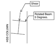
I am designing connections for a small project with rotated beams to accommodate a slope. They EOR and their fabricator decided it would be easier to just rotate the beams to accommodate the slope rather than account for the slope in the connections of the beams on top. After some discussion on this matter, everyone agreed it would be easier to rotate the beams. My question is about the connections for the rotated beams to HSS columns. The beams are rotated a maximum of 5 degrees and the EOR has provided shear end reactions. What considerations for other forces do I need to consider in this situation what is the best way to calculate these forces?
At first I thought about just calculating a moment like this: bf/2 * V = moment, but that seems overly conservative. Then I thought about calculating the distance from the center of the beam with a 5 degree line passing through and multiplying by the shear (that probably doesn't make much sense). dist = tan(5degrees) * d/2, moment = dist * V. That yields a much lower moment. I'm not sure if either method is correct.
Any thoughts on this would be appreciated.

