Continue to Site

Eng-Tips is the largest engineering community on the Internet

Intelligent Work Forums for Engineering Professionals

  • Congratulations cowski on being selected by the Eng-Tips community for having the most helpful posts in the forums last week. Way to Go!

Rotating disc mechanism for a museum display 1

Status
Not open for further replies.

Harper57

Mechanical
Jun 17, 2019
14
Hello all!

I am more of a designer than an engineer, and I joined this group to solicit ideas to solve a seemingly simple problem. I hope this is considered appropriate and I would appreciate anyone willing to help.

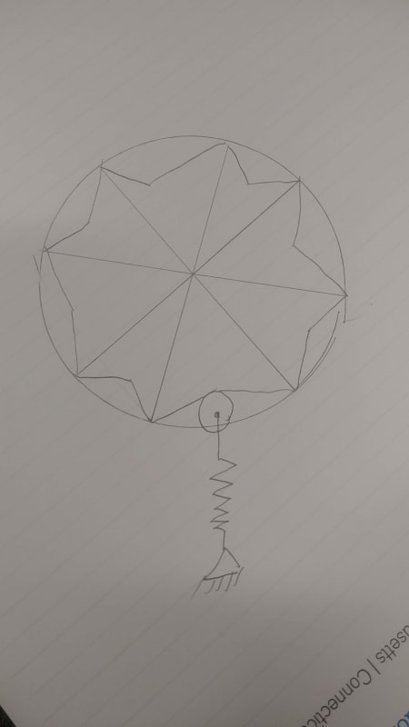
I have been tasked with creating a game spinner device for an interactive display. Think wheel of fortune except the spot you land on is printed on a large disc and revealed through a window, so the alignment must be more precise than just a spinning arrow landing within a pie shaped section, or a fixed flapper that serves the same purpose as on the TV game show. The disc is mounted vertically in a cabinet, and is 38” in diameter, with its mounting shaft captured by two pillow block bearings behind the disc. The idea is that the disc is rotated by the user and as it’s momentum slows some kind of device stops it in one of twelve positions, centering the graphic on the window which is cut out of the front of the cabinet.

I have thought of two ideas. One is a twelve sided cam with a spring loaded arm with a wheel, which contacts the cam. As friction slows the wheel, the spring eventually pulls the arm down, stopping the disc. The wheel would be centered on the facet of the cam, hopefully pushing the disc into proper alignment. This might create a little backwards motion at the end, which is acceptable.

A simpler arrangement would be to drill 12 holes in a radial pattern into the back of the disc, with a spring loaded ball transfer positioned perpendicular to the disc. As the disc is rotated, the ball transfer is pushed back out of a hole, allowing it to ride along the back of the disc, between holes and intermittently popping into and out of the holes, making a clicking sound. When the force of the spring overcomes the force of the rotating disc, the ball transfer goes into a hole like a pin and finally stops the disc from turning.

Any suggestions? Thanks again.
 
Replies continue below

Recommended for you

On the back of the wheel is a cam with 12 flat sides. At rest a lever lies on one of the flat sides, locking it in place. One end of the cam lever has a pivot. The other end is drawn down with a spring, but is also controlled by a shock-absorber/one-direction damper.

If the lever is rotated enough and released the damper allows several seconds before allowing the lever to contact the cam, where it brings the wheel to a stop.

There is a second lever/slide that the user pushes to initially move the cam-lever out of the way and then its remaining movement sends the wheel spinning.

I think the spring can be relatively weak, but it does come with a problem - friction between the cam and the cam lever.

So instead of actual flats, use cam rollers where the corners/vertices would be. This reduces the friction with the lever, decreasing the spring force.

The damper is like is used on storm door closers (it might even be a door closer) that extends easily and loads the spring, and then balances the escape of air to slow the retraction.

Since the user side actuator is a slider the user can't put more than a certain amount of spin on the wheel because the slider can hit a hard stop.

The only other consideration that comes to mind is a second lever with a different distance to the pivot point to minimize the chance of having just enough spin to stop with a roller exactly on the one lever. That way if one lever is exactly tangent, the other one won't be.

PS I haven't drawn any of this up and all advice is worth the payment.
 
IRstuff, I don't want to reinvent the wheel but from my observations the flapper on a wheel of fortune doesn't stop the disc very precisely. Sometimes the wheel bounces back a little. I have text on the wheel that needs to line up neatly with an opening in the front of the cabinet. Still, I'm going to try this, but add a second flapper to limit any backwards travel.

Thanks!
 
Dave, your idea seems like a variation of the cam ides I posted, which the terrific addition of the door closer to allow the wheel to spin a bit before coming the arm brings it to rest. However, I am going to try the simpler solution first. My concerns with that are one, the precision of where the wheel stops, and two, that the wheel may stop turning before hitting the flapper on the last rotation. I'm going to use two flappers positioned directly opposite each other to help align the wheel. Hopefully putting the pins closer to the center of the disc, so they are spaced closer together, will ensure that second problem won't be a possibility. Unlike a wheel of fortune with many pins around the perimeter, I'll only have twelve spaced at 30 degree intervals.
 
Just a brainstorming idea, but how about something like the mechanism in a slot machine (but on a much larger scale)?

Kyle
 
Can you describe how that works? I believe I read that there were pins that go into holes in the rotating reels of older style mechanical slot machines. I guess that's like my spring loaded ball transfer idea.
 
Honestly, I don't really know how they work, but they lock the wheels into precise positions. Of course, I imagine those wheels are fairly light. His disc is 38" in diameter though. I was trying to think of a way to make sure the disc cannot get stuck in between positions.

Kyle
 
If the bearings are sufficiently low friction, you can better the performance of the flippers with strong magnets and steel discs, although the inertia of your wheel would seem to be a significant problem for making it purely passive.

You can potentially mimic WoF's wheel's behavior with 12 magnets and a few Hall sensors coupled with a motor controller.

TTFN (ta ta for now)
I can do absolutely anything. I'm an expert! faq731-376 forum1529 Entire Forum list
 
I was going to suggest magnets, but I was beaten to the punch. Simple, smooth, no noise. Steel plate in the frame, and magnets in the side of the disc. Keep the disc light and depending on the magnet strength, it should work out. You could also possibly move the steel plate further away when starting a spin, then step on a lever to engage it and bring it closer. Maybe the two step user interaction would be more fun?
 
Magnets, sensors, and controllers. With an attached microprocessor you could pre-program it for answers (i.e. cheat - it is a gaming device, no?)
 
The cam lever forces the wheel to stop by brinfing two rollers are in contact with the cam lever. It will be in perfect alignment. If the wheel stops early the cam lever will still come down and force the wheel into perfect alignment.
 
There really can't be any other effort on the part of the visitor except spinning the wheel. So any secondary lever or foot pedal is out. In fact, everything has to be able to be used by someone with a closed fist. ADA standards. But I'm going to marinate in these ideas and let everyone know if I can make it work!
 
I had the ADA standards in mind, but I figured you'd know about them anyway. I have no idea how you got to where you did, as if a machine could not have more than one lever in it, and just assumed that the one that controls the cam would be required to be accessible to the user, but there you are.

See for a mechanism that solves a similar problem.
 
One would use a lever to spin the machine, just like in Vegas; when the lever is pulled down, the wheel spins, and when it's released, it slows down and eventually stops.

TTFN (ta ta for now)
I can do absolutely anything. I'm an expert! faq731-376 forum1529 Entire Forum list
 
"There is a second lever/slide that the user pushes to initially move the cam-lever out of the way and then its remaining movement sends the wheel spinning. "

That's where I got it. The user just spins the 38" dia wheel. That's it. No other action on the part of the user. I did not design the thing, just trying to figure out how to make it work.
 
The action of the user is to move a limb along some path with some minimum amount of force.

That's it.

How that is converted to spinning a wheel that will be guaranteed to end up in one of some several orientations is the problem to be solved.

IRStuff - that's what's shown in the linked video. The slot machines have extra electromechanial items to calculate the payout based on summation of the various dials, but the operation of the dials, where it looks like a spring is tensioned, a damper fan is in place to slow the recoil of the spring, and then a mechanism is applied to lock in an exact orientation, is part of it.
 
Seems like a lot of effort being put into making something simple into something complicated.

Just do this:

20190618_080736_hej8sh.jpg
 
If the wheel is sufficiently low mass and inertia, you could possibly get by with a ball bearing-style detente with sloped approaches, for a completely passive solution.

TTFN (ta ta for now)
I can do absolutely anything. I'm an expert! faq731-376 forum1529 Entire Forum list
 
Status
Not open for further replies.

Part and Inventory Search

Sponsor