Eng-Tips is the largest engineering community on the Internet

Intelligent Work Forums for Engineering Professionals

Rotational Resistance

Status
Not open for further replies.

noobokgbp

Mechanical
Jul 10, 2024
3
0
0
CA
Hi Guys,

I have an application at work where i have to create a fixture for a differential gearset to create a contact patch pattern.

I have to basically apply a 200ft-lb torque on the diff-gear housing against the direction of rotation to bias the backlash to get that contact pattern. I'm thinking of us a BLDC motor to provide the resistance, but i need some assistance because i am not an electrical engineer and have basic mechanical engineering college knowledge of motors. From basic research this sort of thing is possible, however, i need power resisters to dissipate the current as heat from motor. keep in mind the motor is not reversing the direction of motion, rather it is applying a load but still spinning in the same direction that the differential housing is spinning in.

The picture is not an exact representation of my scenario. The cylinder can be considered the diff housing and is spinning at some rpm through the ring gear from the pinion gear. the wheel in this scenario is assuming to not slip and rotating along with the cylinder/diff housing. A motor is attached and applying the negative torque. The -200ft-lbs is applied on diff housing (got this number from our company standards), so the torque required on the wheel will be multiplied by the ratio of radius of diff housing and radius of wheel.

Also note that the contact pattern test is run for around 5 minutes. For this amount of time the motor is applying a rotational resistance. What i mean its not a breaking application. Its a dynamic application.
 
Replies continue below

Recommended for you

If you want torque use a torque motor.
This is a motor designed so that it is able to withstand locked rotor current indefinitely.
Torque motors are often use on cable take-up reels rather than a spring.
I remember one reel with a torque motor that retrieved or laid down about 600 feet of feed cable to a moving bridge crane.
The cable was about 1 inch in diameter. Try that with a spring type take-up reel.
Wound rotor motors may be used as torque motors with a suitable high resistance in the rotor circuit.
An advantage of the wound rotor motor is that the torque may be adjusted by varying the rotor resistance.
At slow speeds the torque motor will develop torque in the chosen direction regardless of the direction of rotation of the driven machine.

--------------------
Ohm's law
Not just a good idea;
It's the LAW!
 
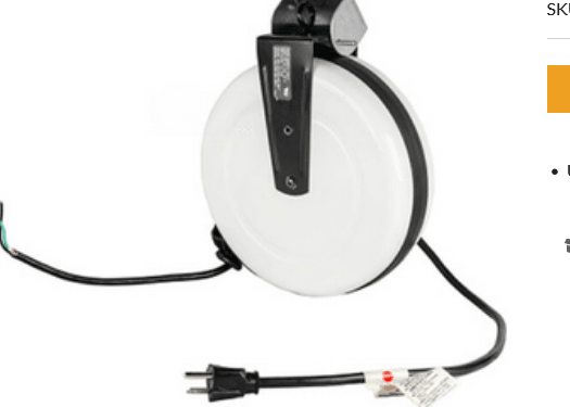
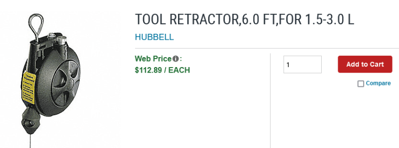
Small take-up reels use a spring.
Applications too demanding for a spring use a torque motor.
Some spring driven reels:

Take_Up_Reel_ldfert.png
HUBBELL_TOOL_RETRACTOR_bhxoas.png


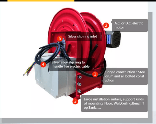
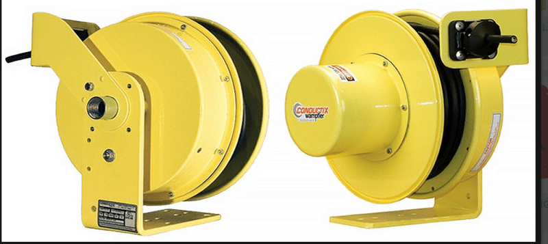
Electric Models

Motorized_cable_reel_flhqns.png
Motorized_Cable_Reels_ugdype.png


Larger reels are often custom designed and built.
Some use a gear box or chain drive between the torque motor and the driven element.

--------------------
Ohm's law
Not just a good idea;
It's the LAW!
 
You may also use a conventional DC motor with a suitable controller.
Details on request.

--------------------
Ohm's law
Not just a good idea;
It's the LAW!
 
A typical DC motor specs.
Torque is dependent on current.
Current is dependent on (Applied voltage minus back EMF) times armature circuit resistance.
Back EMF is directly related to speed.

A demonstration:
Consider a DC motor connected to a dynamometer capable of over-driving the motor.
The motor is supplied by a variable voltage supply.
The motor is rated 1800 RPM at 110 Volts DC.
Permanent magnet field so our numbers are not skewed by field current.
TEST 1:
Apply 110 VDC.
Overdrive the motor until the motor current drops to zero.
This should be at or near 1800 RPM.
The applied voltage equals the back EMF.
Increase the speed and the motor will become a generator.
Typically, a few percent increase will develop full rated current.
Now drop the speed and the current will drop to zero and, as the speed drops further, become a motor.
Typically, a few percent decrease will develop full rated current and full HP.
How many percent?
It varies depending on the resistance of the armature circuit.
The lower the armature circuit resistance, the lower percentage change is needed to develop full current, either as a motor or as a generator.

TEST 2:
Now hold the speed constant and vary the voltage a few percent up and down..
At constant speed, the back EMF is constant, and the armature current is driven between the difference between tha applied voltage and the back EMF.
By varying the voltage up and down a couple of percent, the motor will go from full power motoring to full power generating.

A DC motor, or more accurately a DC machine will go from full motoring to full generating with just a few percent change in either applied voltage or RPM.

To use a DC motor as a torque motor, all that is required is to hold the armature current constant at the desired torque.
The devil is in the details.
This works well with a constant speed load, but in the speed of the load is subject to change, (As we have seen, possibly only a couple of percent) the voltage must be adjusted to keep the torque constant.
A current limiting controller that responds faster than the speed changes may work.
WE have demonstrated that the percent change is dependent on the resistance in the armature circuit.
The resistance of the armature circuit may be increased with the addition of external resistance.
There will be power wasted in the external resistance.
If the resistance is increased by a factor of 10, the overall efficiency will drop to about 10%.
In some small applications this may be acceptable, in other cases, it will be unuseable.

I hope that I have given you enough basic information to solve your immediate task.
At this point, I would be looking at hours and possibly days of research to find existing hardware that fits my needs.
I could get lucky and find something suitable within the first hour, but I will let you do your own research.

There may also be other folk here who are familiar with existing equipment that will be a "drop in" solution for you.
Stay tuned.


--------------------
Ohm's law
Not just a good idea;
It's the LAW!
 
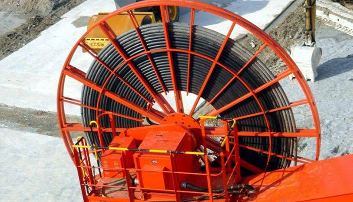
A large motorized cable reel for a port crane application. Old school often used magnetic or hydraulic torque converters. Now they tend to use VFD's and motors rated for continuous zero speed operation.
GantryCableReel_hbknij.jpg
 
There was no picture. What rpm and hence power level?

I would possibly look at an AC induction motor and a line regenerative VFD. You just tell the VFD to run at a speed a little below the free spinning rpm and the motor will load whatever is driving the motor shaft. The energy is put back into the power system so you can use it to drive the pinion. That way, the only energy lost is the losses of the system, maybe 10-15%. Problem is that your power level is likely too low for this to be practical. But, you could also do it with a VFD and a resistor, it would just dump the energy into heat.
 
Do you have three phase power available?
A standard 600 Volt motor fed with around 50 Volts or 60 volts will probably work.
he problem is calculating sizing.
But, if you have any spare motors available it may be worth trying.


--------------------
Ohm's law
Not just a good idea;
It's the LAW!
 
That's true, an oversized motor being run backwards with a voltage controller or even having variable DC applied to it would create a load. Both are fairly low tech solutions.
 
Both are fairly low tech solutions.
Worth considering?
It depends.
Buying new may be pricey.
If you have suitable motors on hand in the maintenance department stores, it is probably worth trying.

--------------------
Ohm's law
Not just a good idea;
It's the LAW!
 
Status
Not open for further replies.
Back
Top