Eng-Tips is the largest engineering community on the Internet

Intelligent Work Forums for Engineering Professionals

Round-ify elements along a curve 1

Status
Not open for further replies.

RyanWard

Mechanical
Mar 2, 2023
7
0
0
US
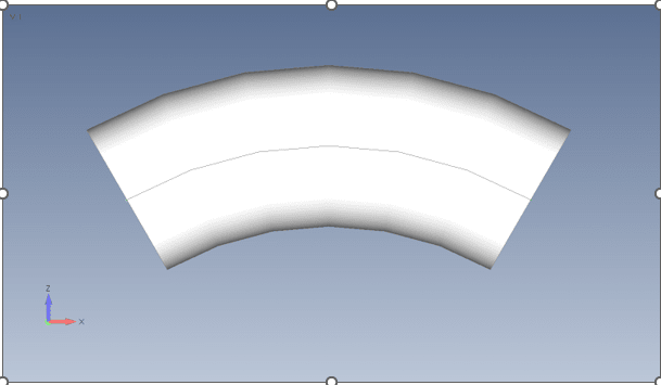
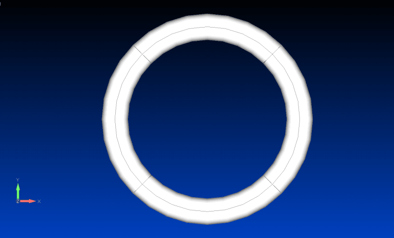
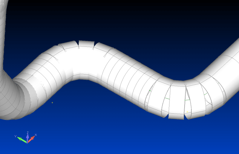
I'm modelling a pipe run and when the element thickness/cross-section is visible, the elements are just portrayed as straight partial tubes oriented along the curve of a bend. How do I apply the curve of the pipe bend (for which I have a centerline imported as geometry) to the elements for visual-sake? I've seen this done before but I just can't find anywhere how to do it. See below.

grab_hdvj0v.png
 
Replies continue below

Recommended for you

what code ?

you're using a "pipe" or beam element, and showing the elements cross section ?

I don't think you can make this continuous. If you had modelled the surface of the pipe, then the elements would be continuous.

"Hoffen wir mal, dass alles gut geht !"
General Paulus, Nov 1942, outside Stalingrad after the launch of Operation Uranus.
 

I'm using a beam with a circular tube cross-section. I used a centerline imported as geometry and meshed along the centerline. This is how I've been instructed to do these sorts of analyses. I've seen smooth bends, like the elements have been swept along the curve, using this same method. I was then instructed to curve the elements along the curve of the centerline bend for visual purposes, so it looks more like a pipe when presenting the results.
 
I get what you're doing, and it seems sensible. To get a good image, I'd model the pipe surface, only for viewing (keep the beam elements).

But you're saying you've seen a continuous pipe from this type of modelling ... ok, maybe someone who knows will chime in. Blas ?

"Hoffen wir mal, dass alles gut geht !"
General Paulus, Nov 1942, outside Stalingrad after the launch of Operation Uranus.
 
Femap/Nastran supports Curved Tube element (but not supports straight tube element). But this is special purpose element, it designed specifically to calculate pipes according to common pressure vessel codes.
Here it is, in element selection menu.
Image_001_igypo3.png


If you don`t perform some pressure vessel calculation, then I recommend don`t bother with this element and use regular BEAM element. BTW I don`t certain that Curved Tube element has proper visual representation in Femap, it may look like thin curved line without thickness.
I don`t work with this element just read about it some time ago on this forum or on Siemens community. Blas had written about this element.
 
In addition to karachuns comment there is a Curved beam element. You can see that on top of the right column in the same figure as the "Curved Tube". But I don't know the exakt behavior for it since I have never used it [smile]. But if you really want to model the "curved behavior" for a pipe, why not use plate elements?
 
yes, but do these curved elements show a continuous surface with viewed ? OP is viewing element shape (I suppose).

"Hoffen wir mal, dass alles gut geht !"
General Paulus, Nov 1942, outside Stalingrad after the launch of Operation Uranus.
 
ok, I see the OP was using piecewise linear beams ?

"Hoffen wir mal, dass alles gut geht !"
General Paulus, Nov 1942, outside Stalingrad after the launch of Operation Uranus.
 
maybe the problem is he should be using curved beam element (not piece-wise straight) ?

"Hoffen wir mal, dass alles gut geht !"
General Paulus, Nov 1942, outside Stalingrad after the launch of Operation Uranus.
 
Thanks for all the feedback. I've deleted the elements and mesh along each curve and applied a curved beam type. However, the mesh still remains un-continuous as seen in my initial post image despite now being a curved beam type.
 
Well, the instruction I received on how to do this was wrong and I should have used bent tube element type, so I did that and it's working as it should now!
 
Curved_beam_uae7ym.png


I have now created a circle using 4 curved beam elements. The procedure was to start with 4 nodes in a square, 1 x 1, and connect the 4 nodes with 4 elements. That means that the diagonal in the square is the diameter of the circle, sqrt(2), and the radius for the curved beam element is sqrt(2)/2. You also need to check the orientation for each element.

But unless this is some requirement due to something specific for this analysis. Skip the curved beam and use a finer mesh at the curves, I agree with Blas. And if there is some special requirements, don't you need plate elements?

If the only purpose is for things to "look nice", that is not a good argument in my opinion [smile].
 
Status
Not open for further replies.
Back
Top