Continue to Site

Eng-Tips is the largest engineering community on the Internet

Intelligent Work Forums for Engineering Professionals

  • Congratulations waross on being selected by the Eng-Tips community for having the most helpful posts in the forums last week. Way to Go!

Running MV/HV Cables in Flat Formation vs. Trefoil 2

Status
Not open for further replies.

Power0020

Electrical
Jun 11, 2014
303
Running cables inside substations in trefoil formation ensures balanced voltages; however, due to ampacity requirements, flat formation proves to be more economical.

What is the criterion to select running cables in flat vs. trefoil other than ampacity?

Regarding voltage unbalances in flat formation,it appears very similar to running a 220 kV bus with flat tubular bus, I have never seen anyone cares about unbalance voltages at the level.

However, with MV cables on 11 kV (13.8 kV), A power transformer may be connected to switchgear with flat cables, usually with multiple runs per phase, I doubt the unbalance may be reasonable.

Any similar experiences or calculations references?
 
Replies continue below

Recommended for you

Usually underground transmission lines and MV distribution feeders are much shorthers similar overheads lines. Voltage imbalance is a function of line length. For short line voltage difference is not an issue.
For underground cable the shielding method are usually more relevant than the phase voltage difference.
 
For short cable routes, for example within a substation, you can use single point sheath-earth bonding. At the unbonded end, you have a voltage rise to earth on the screen which is proportional to the current flowing and the length.

To get the rating benefit of the increased cable spacing with flat formation, you would probably need to use single point bonding. If you bonded the screens solidly at both ends, the increased circulating current in the screens would act to cancel out the benefit of flat formation.

Regards
Marmite
 
The voltage unbalance is proportional to the difference in phase impedance and the current. The phase impedance difference in ohms doesn't depend much on the voltage. So, for a given current, the voltage unbalance in volts will be about the same, but the voltage unbalance in percent will be lower for a high voltage system than for a low voltage system.
 
The power cable shield help to mitigate the voltage unbalance caused by the mutual electromagnetic effect between the cable even for flat configuration. In my experience unbalance voltage for power cable is rare and only relevant in long overheads transmission line were line transposition is used to mitigate the voltage unbalance.

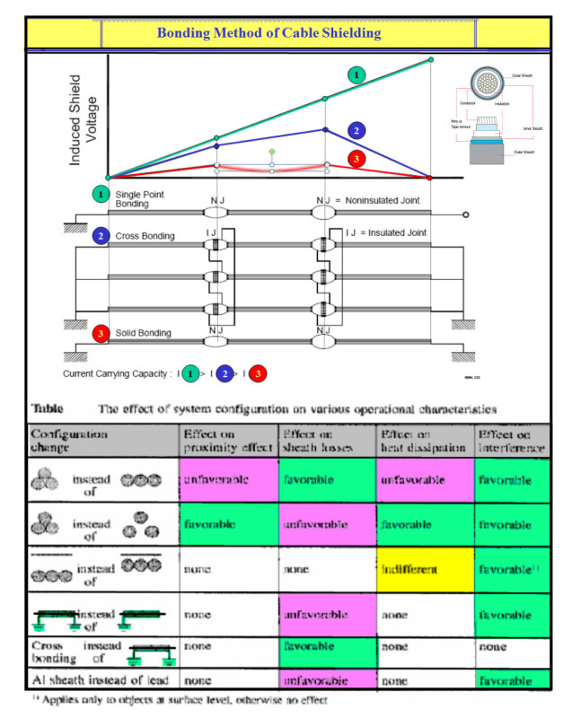
Power0020, there are fundamentally 3 types of HV power cable shielding method: One end-grounded,both ends-grounded and cross bonding. Sometime variation with surge arrester (shield voltage limiters) are used. Below is an excerpt from various sources captured in a table and a generic plot with additional info of cable performance for flat and trifoil configuration.

Hope this help.

Power_cable_shielding_gy2pgu.jpg
 
Great as usual cuky2000, many thanks for that. I know the shielding by its other name, sheath bonding!.

May you please upload the photo in a file form, the text is unreadable.

 
I understand that the cross bonding current rating is equal to the one with single point bonding.

I assume that it can go less than the single point bonding in case of unbalance in minor section lengths raising some circulating amps?
 
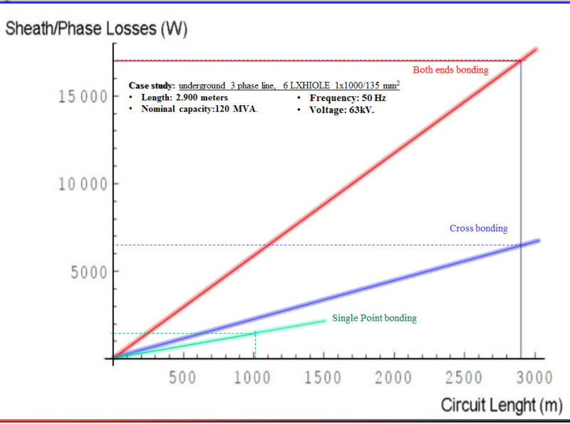
Hi Power0020: At difference than the cross bonding, there is not current path to ground (earth) for a single point bonding. However, in both cases there is Eddy current but this is much smaller than the circulating current. This can be reflected in the cable losses shown in the generic graph below.
Per your request, a readable pdf file is uploaded.
Cable_Sheath_Losses_zafczt.jpg


Status
Not open for further replies.

Part and Inventory Search

Sponsor