Eng-Tips is the largest engineering community on the Internet

Intelligent Work Forums for Engineering Professionals

  • Congratulations waross on being selected by the Tek-Tips community for having the most helpful posts in the forums last week. Way to Go!

SCBF with all HSS members 1

Status
Not open for further replies.

dozer

Structural
Apr 9, 2001
502
0
16
US
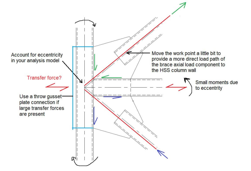
I'm designing a structure with HSS columns, beams and braces in a high seismic area. I would like to use a SCBF to reduce the seismic design load. All the examples I've found use WF columns and beams with HSS braces. This is a tall piece of equipment that doesn't lend itself well to WF's. Has anyone done something like this before? I'm thinking of using a gusset plate to connect the braces to the beam and column but I'm not sure the column can handle the gusset plate load. I'll try running some numbers tomorrow but I was hoping somebody has been down this road before and can give me some tips.

I did think of running the plate all the way through the column but this has another wall framing into it at 90° so that wouldn't work. Besides, the shop would hate me if I did that.

Link
 
Replies continue below

Recommended for you

This is only to pass my limit understanding on this subject, when SCBF allows higher R value to reduce the design load, be aware there could be a catch later, that panelize the design at the detailing stage that pushes for ductility. Suggest to check detailing requirement before making your decision.
 
good observation by retired13, the connection design can be a killer on these systems. Looks like dozer already has the gusset drawn to allow a plastic hinge. There may also be some capacity based requirements for your connection where you need to design for the probable strength of the brace.

You might be able to get the connection to work as shown - since your gusset runs through the beam then a majority of your brace force is direct transfer between braces. The driving force in the gusset to column connection should be the vertical from the beam and bracing.

Depending on the size and quantity of the columns, W shapes might win over HSS just to simplify the connections. W shape columns would allow easier bolted connections if that is of any benefit.
 
HSS shapes are perfectly acceptable as column elements in SCBF pending they meet the ductility requirements. Table 1-5 in AISC 341 can give you a quick idea of what shapes meet those requirements. I've never used HSS elements as beams in a SCBF but again I would imagine as long as the shapes meet the ductility requirements it's acceptable to use them as beams.

Are you designing the actual connections or are they a delegated design?
 
Basically agree with everything Boof19 says and have had the same experience.

Gusset to face of an HSS is an area to address, whether it's a column or a beam it doesn't really matter, but there are plenty of options to achieve the capacity you need. Thicker HSS wall, thicker gusset, longer gusset length along column, knifing the gusset.

Knifing a gusset in an SCBF is not uncommon, although you seem to think this is not an option here. More expensive, yes, but definitely possible.
 
Thanks for the responses so far. Sorry to take so long to get back but for some reason I'm not being notified so I thought nobody cared. I did check the gusset attachment to the column and it looks doable but some other issues are raising their ugly head.

Retired13, you correctly guessed that this would be panelized. It will have 3/16" plate welded to the outside to close it off. I was going to consider this just an extra added bonus to make it stiffer but not consider it in the analysis. I figured if a weld broke or the plate buckled it wasn't being relied on anyway. Maybe that's bogus thinking.

There are capacity based requirements and I'm finding this is a killer for the columns. This structure will be nearly 160' tall. By the time you add up all the brace forces I get about 2400 kips in the column at the base! This is larger than I get just biting the bullet and not using a SCBF! Although it is looking like I will save a lot on braces. I'm starting to wonder if it's worth it though.

The other issue I'm perplexed by is the requirement for the beam-to-column connections. AISC 341-16 Section F2.6b(b) says:

(b) The connection assembly shall be designed to resist a moment equal to the lesser of the following:
(1) A moment corresponding to the expected beam flexural strength, RyMp, multiplied by 1.1 and divided by αs
(2) A moment corresponding to the sum of the expected column flexural strengths, Σ(RyFy Z), multiplied by 1.1 and divided by αs

I'm not sure what number 2 is. Can someone explain that? If it's not the lesser though, it seems like it would be very hard to pass number (1) with tube on tube. I guess I should run some numbers on that too, huh?

I would appreciate any more thoughts on the subject. I'm not feeling too good about it at the moment.
 
Hi dozer,

I suppose your biggest concern is about the transfer of forces between the gusset plate and the wall of the HSS column. I have attached a sketch of an alternative and more direct load path that requires a small modification in the work point. I would do the following:

1) Move the workpoint so that the vertical and horizontal components of each brace axial load are transferred directly to the column and beam walls respectively. That way, there is not bending and punching shear in the HSS column wall, only shear in the plane of the wall. This is, in fact, the Special Case 1 of the Uniform Force Method in the AISC Steel Construction Manual.

2) Account for any eccentricity in your analysis model.

3) If large transfer forces are expected, use a throw gusset plate to transfer the load directly to the beam.

Hope this help!

 
Sorry, here is the sketch

SCBF_HSS_c03qsw.jpg
 
dozer said:
The other issue I'm perplexed by is the requirement for the beam-to-column connections. AISC 341-16 Section F2.6b(b) says:

(b) The connection assembly shall be designed to resist a moment equal to the lesser of the following:
(1) A moment corresponding to the expected beam flexural strength, RyMp, multiplied by 1.1 and divided by αs
(2) A moment corresponding to the sum of the expected column flexural strengths, Σ(RyFy Z), multiplied by 1.1 and divided by αs

I'm not sure what number 2 is. Can someone explain that? If it's not the lesser though, it seems like it would be very hard to pass number (1) with tube on tube. I guess I should run some numbers on that too, huh?

AISC 341 requires that gusseted beam-to-column connections be designed to accommodate demands corresponding to large drifts. This effect is also known as frame distortion or frame action. Two methods to accommodating demands corresponding to frame distortion are provided in AISC 341. In the first method, as described in Section F2.6b(a), the connection may be detailed to provide sufficient rotation capacity such that the beam and column are not constrained to rotate together as the frame deform. The required rotation capacity is 0.025 rad, which can easily be accomplish with a simple connection designed and detailed according to the AISC Steel Construction Manual.

The second method is described in Section F2.6.b(b). This method establishes an upper-bound demand based on flexural yielding of either the beam or the column. The connection is designed to resist a moment corresponding to the lesser of 1.1 times the expected beam flexural strength and 1.1 times the sum of the expected column flexural strength above and below the connection. This moment must be considered in conjunction with the brace forces corresponding to their expected strength. The connection may be designed to resist this moment in one of two ways. One of these ways is to analyze the entire assembly (reinforcing beam column) with the required moment following the procedure described in Section 4.2.6 of the AISC 29 Design Guide. The internal forces determined from this procedure must be combined with the internal forces resulting from each brace axial load.

I would go for the first method described above, that is, I would detail the connection to provide the required rotational capacity. A way to accomplish this requirement is to made a bolted splice in the beam away from the connection. This splice may be detailed as a shear end plate and designed considering the provisions of Part 9 of the AISC Manual to provide enough rotational ductility. Note that shear connections similar to those presented in the Part 10 of the Manual and meeting the rotational ductility checks described in Part 9 of the Manual can be assumed to provide a minimum of 0.03 rad. Attached is a sketch of the proposed detail.

Bolted_shear_splice_vg4wck.jpg
 
Proyector, thanks for all the effort you put into this. I looked into the beam-to-column connection some more and I determined that for our case where the overall size of the column matches the beam you can't get a moment connection of a HSS welded directly to the column to work. For example, if you go with both being 8x8 the largest available wall thickness is 0.625" (0.581" design) so let's use that for the column. Setting equation K3-7 in AISC 14th ed. equal to 1.1RyMp, we get that the column can handle a tube with a Z up to 24.16 in^3. So the largest beam the column could handle is a HSS 8x8x1/4", but anything this size or smaller doesn't meet the b/t requirements for highly ductile members necessary for a SCBF.

It looks to me like IF you want to use size on size and IF you want to use bm-to-col moment connections then HSS is not a viable alternative for SCBF.

Regarding you simple beam connection, this frame will be covered with plate welded directly to it, which, I know, throws a monkey wrench into the whole thing analytically anyway but that would be difficult to fit around that shear connection. Not to mention that would screw up it's rotational freedom.
 
Hi dozer,

From what you say, it sounds like it's about a nonbuilding structure, I am right?
In my experience, nonbuilding structures often impose many constraints that make using a high level of seismic detailing (like SCBF) impractical and/or inadequate. For example, welding plates directly to the frame would cause the SCBF to be unable to achieve its intended performance.
So, I would choose an OCBF instead of an SCBF. Yes, the seismic demand will be higher (in the brace elements, at least), but the overall cost of an OCBF structure is often much lower compared to SCBF.

 
I would choose an OCBF instead of an SCBF. Yes, the seismic demand will be higher (in the brace elements, at least), but the overall cost of an OCBF structure is often much lower compared to SCBF.

Well said.
 
Yep, it's a nonbuilding structure. It' in seismic design zone E and over 150' tall, so I can't use OCBF. Looks like I'll have to bite the bullet and use R=1.5. Ouch! I was ignoring the elephant in the room, the plate welded to the outside. Thanks, Proyector for pointing out that would cause the SCBF to be unable to achieve its intended performance anyway.
 
Status
Not open for further replies.
Back
Top