Continue to Site

Eng-Tips is the largest engineering community on the Internet

Intelligent Work Forums for Engineering Professionals

  • Congratulations SSS148 on being selected by the Eng-Tips community for having the most helpful posts in the forums last week. Way to Go!

Scissor Trusses 1

Status
Not open for further replies.

SteelPE

Structural
Mar 9, 2006
2,759
We are currently working on a wood framed building with scissor trusses. We are responsible for the design of the structure as a whole and a wood truss manufacturer is responsible for the design of the scissor trusses. Code is IBC 2015. The spans of the scissor trusses are quite long (40'-0").

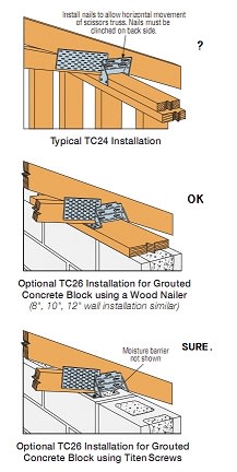
When speaking to the truss manufacturer with regards to the design of the connection of the truss to the top of our wood walls we are being told to use a Simpson TC26 (diagram attached). We have some concern with regards to this connector as we are requiring the truss to provide stability at the top of the wood wall.... and if the connection is allowed to slide then we will lose that stability.

Is it common for wood framed buildings that use scissor trusses to use this type of connector (Simpson TC26) and just ignore the stability concern.... or do you use a different connector that inhibits lateral movement of the truss?

The truss manufacturer has not been helpful at all with this project to the point of being combative. They are basically saying that it's up to us to solve this issue and they do not want to change their design around. It is not making for an easy project
 
 https://files.engineering.com/getfile.aspx?folder=f4aed3bf-00dd-4cf7-93bb-18224ce2a657&file=C_TC24_2DP_Cad_ISO_Instld.pdf
Replies continue below

Recommended for you

No, you can't just ignore it. These are really handy if the wall is getting its stability from somewhere else - such as a lower roof diaphragm or ceiling framing into it. It lets you release the horizontal truss reaction that would otherwise form.

If you don't have any other source of stability for the wall, you'll need a "pin" connection. You'll just have to make sure the wall is sufficiently flexible (and its finishes) to undergo the deflection that the truss needs to see to prevent stress reversals.
 
I have been down this exact road before ... If one do not allow for movement at one end (pin/pin) and the supports are truly rigid, then the forces within the truss member become problematic. I have had zero success with any truss suppliers providing me with a pin/pin design. I even said that cost was not an issue, upgrade the top and bottom chords, whatever, and they continually came back and said no. TPIC confirms this in their truss design guide. The more popular truss design software packages they use will not allow them to change this option.

What I have seen done numerous times.
1) For standard walls, let the contractor use the clips. There seems to be enough friction, and there is about a 1-1/2" limit on the movement, that there does not appear to be any negative consequences. Why the drywall doesn't crack ... I don't know. (Tall walls need more consideration)
2) I have seen engineers specify a staggered installation of the connectors. Truss 1 gets the connector on the west side bearing, Truss 2 gets the connector on the east bearing, and so on. Seems to me that the sheathing would inhibit the movement the connectors could provide, but again ... it's done all the time and I have not seen any negative consequences.
3) Most contractors grumble about having to pay the extra $$ to install the connectors, then as soon as the building inspector leaves, they nail them all in place to solidly fix them. I am not condoning this, just pointing out the fact that this happens regularly.

My thoughts are that pretty much any wood framed wall can move a bit laterally as there is little restraint (2 ply top plate with joints all over the place). I think that the drywall does not crack at the joints where the connectors are because friction is keeping the truss mostly in place relative to the top plate and the top of the wall moves in and out 1/4" or 1/2". I typically see the truss companies asking for 3/4" lateral movement to be accommodated, and that would be under the most extreme snow load conditions which is rare.

After delving into this in the past, and seeing what has been previously built, I have come to the conclusion that I worry very little about this issue and let them install these connectors, in regular residential applications.
 
1) In order to benchmark my experience, I used to be a metal plate connected wood truss designer. I also used to work for the Wood Truss Council of America although, it's important to note, I do not represent them in any way now. I've also been the EOR on a lot of projects involving scissored metal plate connected wood trusses.

2) I've not once seen a scissored truss that lacked an end slip connection cause a real world problem. There are many possible explanations for that, all of them difficult to quantify:

a) Loads are overestimated.

b) Deflection is overestimated.

c) Diaphragm restraint.

d) Walls are flexible away from wall corners.

e) Diaphragms are extra stiff near wall corners.

f) A good truss designer will push for a bottom chord pitch not much more than half of the top chord pitch which tends to limit deflections a bit.

3) Personally, I always ignore this issue and never provide the connectors so long as the truss configuration and deflections are not stupid seeming.

4) To me, the connectors seem to garner one little if anything of benefit, annoy contractors and incur cost, and often create that wall restraint issue that you mentioned. Lose-lose.
 
and if you don't, the warranty is likely voided.

Rather than think climate change and the corona virus as science, think of it as the wrath of God. Feel any better?

-Dik
 
I'd suggest you first determine how much lateral movement you can tolerate at the top of wall, then specify that the lateral deformation at the reaction be less. Their calculation will show the deflection at the roller support, but the walls may splay out equally on both sides. So, if the calculation shows 1 1/2" lateral deflection at the support, but you think that 3/4" on each side would be too much, then you need a stiffer truss.

They won't/can't design pinned-pinned, and that wouldn't be realistic given that you can't provide that restraint with this construction. The sliding connection isn't realistic, because it's not a frictionless surface, so the wall will move with the truss anyway.

I favor canuck65's example of alternating the clip. That way, you can show that the top of wall is periodically braced, and they can live with the fantasy that the truss slides at the bearing.
 
kipfoot said:
That way, you can show that the top of wall is periodically braced, and they can live with the fantasy that the truss slides at the bearing.

And what a fantasy it is. With a sheathed roof diaphragm, a slip connection at every second connection pretty much guarantees no meaningful slip at any connection. In a way, I feel that the alternating hardware actually makes things worse as you basically force the movement tendency of two trusses through a single truss then. In situations where the bearings would provide lateral restraint, you'd be doubling the risk of shearing through your toenailed connections.

I find the fact that these Simpson slip connectors exist very discomfiting. They seem patently ridiculous to me but, at the same time, Simpson is consistently awesome at every technical thing that they do. Makes me wonder if it's me that's crazy or if the marketing team over at Simpson bullied this thing into existence.
 
I've done one design with scissor trusses in my life and stressed out mightily on it.
Somewhere I got the procedure attached and implemented it. It's relying on most of the loads being dead loads and some really challenging directions to the wood truss designer. Unlike you folks, I didn't make the mistake of asking them.
That was six years ago and I haven't got any panicked calls, so I'll say it was OK.

Wait a minute, my phone is ringing.
 
 https://files.engineering.com/getfile.aspx?folder=dc001a5e-a3cd-42a9-8bda-07e112c5bac9&file=Scissor_Trusses.jpg
So it looks like we are dammed if we do and dammed if we don't.

This building isn't a simple box..... it's L shaped with the scissor trusses over one portion of the leg of the L. There are canopies on this building as well, but they are not overly wide.... certainly not wide enough to comply with any type of aspect ratio as set forth in the NDS.

One other issue is that these trusses are supported by the perimeter walls, which also provide wind and seismic stability to the building by utilizing WSP shear walls. So, transferring the lateral loads from the roof diaphragm to the perimeter walls is an issue as well. We have spoken to the truss manufacturer about this and have come up with a way to get the loads out of the plywood roof diaphragm, but that requires blocking in-between the trusses with will need to be nailed to the top plate of the perimeter wall.

The architect hasn't been helpful at all. They are completely clueless to the situation. It took me 20 minutes to explain what was going on but still don't think they understood what I was saying after repeating myself a dozen time to the same question phrased differently.
 
Jed - were you actually able to verify that they complied with all that?

SteelPE - what kind of deflections are you ending up with at the "slip connection" in their calculations? And how tall are the supporting walls?
 
KootK said:
In situations where the bearings would provide lateral restraint, you'd be doubling the risk of shearing through your toenailed connections.

I'm interpreting the OP's situation as one where there isn't, and can't be, a wall that's stiff enough that the truss would slip across the top plate. I don't see (yet) how it's worse than clips all on one side in this situation because you still want to show that the wall is pinned at its top.

I could see these being effective with trusses bearing on masonry or concrete walls.
tc24_turx3r.jpg
 
kipfoot said:
I'm interpreting the OP's situation as one where there isn't, and can't be, a wall that's stiff enough that the truss would slip across the top plate.

Most wood framed buildings will have wall corners and intersection with interior walls creating locations of lateral restraint. This effect, of course, mingles with diaphragm action in most cases.
 
kipfoot said:
I could see these being effective with trusses bearing on masonry or concrete walls

Those clips are only effective- ish if the wall is designed to be free-standing. Otherwise, there is no out-of-plane restraint at the top of the wall.
 
KootK said:
I find the fact that these Simpson slip connectors exist very discomfiting. They seem patently ridiculous to me but, at the same time, Simpson is consistently awesome at every technical thing that they do. Makes me wonder if it's me that's crazy or if the marketing team over at Simpson bullied this thing into existence.

No, you are not crazy. These clips are stupid and serve no purpose other than to make Simpson a lot of money.
Also, what happens to the sheetrock when the truss flairs out, but the "freestanding wall" does not?
 
phamENG said:
SteelPE - what kind of deflections are you ending up with at the "slip connection" in their calculations? And how tall are the supporting walls?

The deflection varies depending on what truss we are specifically looking at. The structure is a retail building meant to look like a barn. Therefore there is a huge cupola in the middle of the building. So we have a few girder trusses in the building. There is a mezzanine on one end as well where the girder truss is taking the load from the roof (this is the where the largest movement is anticipated) The typical truss is showing a .8" deflection. The girder trusses go up to 1.17 inches. Wall height is 10'-0" +/-

I would have like to have been out in front of this project, but someone above me dropped the ball. We were asked to develop the proposal over 3 years ago. Then we were told the project has been a go every year since. So, when we were told the project was a go in December we put it in the que..... but the GC (who has already been brought on board) had gone out an gotten the truss design already completed. I think the owner didn't want to pull the trigger until they had full approval from the jurisdiction... once they received approval the owner expected the design team to hit a button on their computers to produce a full set of drawings. We have been proceeded to be scolded for not getting the project done fast enough when in reality we have been jerked around for 3 years.

Sorry to vent. :)
 
SteelPE said:
We have been proceeded to be scolded for not getting the project done fast enough when in reality we have been jerked around for 3 years
One very important lesson I was fortunate to learn early on in my career was that clients will always try to make their problems your problems, and while you may feel obliged to take on that problem, you shouldn't. That's not to say that you shouldn't ever help a client out! But when they come to you at the 11th hour, when they were the ones who had stalled - leading to this annoying situation in the first place - you really shouldn't feel obliged to do anything especially if they are acting like they've done nothing to lead to the situation.

My life has been considerably better since I stopped caring when clients did this kind of thing...which is often.

 
SteelPE - no worries. I'm likely facing a similar situation (though the time frame is in the months range rather than years) in the next few weeks.

I wouldn't be overly concerned with the 0.8" deflection. If you pin both ends and the wall construction is the same on both sides, you can reasonably expect 0.4" at each end. If you consider it as a cantilever deflection, you're sitting at about 2L/600 - not bad at all. Even at your girder truss, it comes out to be 2L/407.

Maybe work with the architect to hide the joint between the ceiling and the wall - some sort of trim or something - just in case it cracks. But it's likely okay.
 
Status
Not open for further replies.

Part and Inventory Search

Sponsor