Eng-Tips is the largest engineering community on the Internet

Intelligent Work Forums for Engineering Professionals

Screed Table 1

Status
Not open for further replies.

tmalik3156

Structural
Jun 21, 2021
92
0
6
CA
Good day all.

I am required to prepare a table of screed elevations for a bridge deck. These are the steps I am thinking of in my calculation. Kindly advise if this is correct and complete.

Step 1: From proposed final roadway centreline elevations, subtract thickness of asphalt to get top-of-concrete elevations. Do this for ten points in one span. These are screed points.

Step 2: Do a structural analysis of the centre girder (bare girder only – not composite) subjected to following dead loads. Use the girder’s tributary width for the weight of wet concrete and weight of asphalt. Also include the parapet and sidewalk weight (assumed smeared equivalently over the entire deck) in the girder’s tributary width.
(Some people say only include wet concrete weight ??)
Find the deflection at each of the screed points.
Do not include girder self weight. This is because girder self weight deflection is already included in the camber.

Step 3: Add these deflection values to the top-of-concrete elevations of Step 1. The resulting elevations are screed point elevations above the center girder.

Step 4: From known transverse slope of the deck from the center (crown), calculate screed elevations along other lines of girders, and along the edge of the parapet (where screed rail will be placed).

If anyone can share guidelines, spreadsheets, or example calculations, that will also be much appreciated

Thank you
 
Replies continue below

Recommended for you

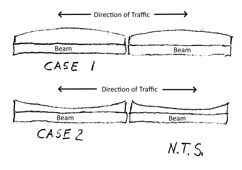
I believe you have it covered. Of course you want to get the settings exactly right, but if there is an error, make sure it results in a surface profile like Case 1 (shown below). Including everything in the calcs is the best way to make this happen. A surface profile like Case 2 rides "terrible" and will result in an endless stream of complaints. The same magnitude error in Case 1 is, for some reason, is not considered nearly as bad a problem.

Advice straight from my father (highway bridge construction management 1935 - 1976) to me.

Bridge_Deck_Screed-500-1_tfr4ag.png


Edit: Relabeled sketch to clarify that this is a longitudinal section of bridge deck.
 
If the superstructure will be composite, we use the composite section properties to calculate deflections for parapets, curbs, sidewalks, railings, etc. - anything that will be added after the deck has cured.

For superstructures with fairly stiff crossframes or diaphragms with the connecting bolts fully tensioned, we typically calculate the average dead load deflections for all the girders at the tenth points of each span, and add them to the finished grade (top of concrete) elevations along each girder. Alternately, the total load and the sum of the moments of inertia of all the girders could be used.

We provide screed elevations along each girder, the edges of the deck, at any longitudinal staged construction joints in the deck and the crown point of the deck (if there's not a girder there).

Were the camber calculations/web cutting done by someone else? For our designs, the web cutting and screeds are part of the same design. For rolled sections (Wide Flange), without cambering, we provide a slab thickness diagram, in lieu of screed elevations.
 
@SlideRuleEra: Thank you very much for your reply. We will definitely try to avoid Case 2, which could create a water pond in summer and an ice rink in winter.

@BridgeSmith: Thank you very much for the detailed reply. We will use bare girder in the computer model to determine wet concrete (deck and haunch) deflection (delta 1). We will use composite girder to determine superimposed deadloads (asphalt, parapet, sidewalk) deflection - delta 2. To simulate composite action, we will modify the Second Moment of Area (I) of the bare girders by a multiplier. This multiplier is the ratio of (I_comp / I_bare). In computing I_comp, We will use long term concrete Modulus of Elasticity, which is about a third of the initial concrete MOE. We will add the total deflection (delta 1 + delta 2) to the proposed top-of-concrete elevation to get the screed elevation.

This is a rehab bridge where we are re-using the 40 year old girders. So we won't prepare a camber diagram. Instead, the contractor will provide us the top-of-girder elevations once the existing deck is removed and the girders rebound.

Nowhere will we calculate and add the girder self-weight deflection, because the girder will already be standing there deflected by its own weight. Hope this makes sense.
 
Makes sense, tmalik3156. The deflection calculation you describe sounds right to me. We typically just use 3 times the modular ratio (3n, where n = Es /Ec) to transform the concrete to an equivalent area of steel for the calculation of I-comp. For calculation purposes, essentially, we add a 'steel cover plate' that is the height of the slab and 1 / (3*n) of the effective concrete flange width.

The rest of the approach also makes sense for redecking on existing girders.

Just a note about adding shear studs in the field - installing automatically end-welded shear studs takes a very large arc welder and an even larger generator. If that is your intention, make sure a rig capable of doing the work is available.
 
BridgeSmith said:
We typically just use 3 times the modular ratio (3n, where n = Es /Ec) to transform the concrete to an equivalent area of steel for the calculation of I-comp. For calculation purposes, essentially, we add a 'steel cover plate' that is the height of the slab and 1 / (3*n) of the effective concrete flange width.
That's a clever way to do it, thanks.
 
Status
Not open for further replies.
Back
Top