Eng-Tips is the largest engineering community on the Internet

Intelligent Work Forums for Engineering Professionals

Screw Torque Specification/Calc

Status
Not open for further replies.

MEngg111

Bioengineer
May 23, 2023
2
0
0
US
Hi.
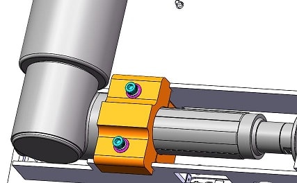
We have an actuator clamp top and bottom (SS) designed that holds a linear actuator in place and I need help with determining/calculating torque specification (in-lb) on the two screws that secure this assembly.

I have attached an image here of the assembly.

Bolt specification:
10-32 UNF 2A, SHCS
L= 2 3/8"
Material= 18-8 SS
(No special coating)

This linear actuator would be exposed to ~850 lbf and I want to ensure the screws secure the clamps adequately. Please help with determining what torque spec should be specified here.

If additional information is needed please message here. Thank you.
 
 https://files.engineering.com/getfile.aspx?folder=71e7166b-ce76-4b15-bac6-06406d5407d7&file=Linear_Actuator&Clamp.JPG
Replies continue below

Recommended for you

The filename with the "&" in it isn't easy for users to download - internet addressing reserves "&" for special purposes. Not sure why the forum software allows uploading files with those names.

In any case - the typical goal is to produce an elongation in the bolt enough to be at 80% of yield strength and that elongation can be determined best by the amount of turn after the fastener is seated be dividing the elongation by the thread pitch. Use a torque of a few inch pounds to settle the fastener into place and then turn the bolt as per the elongation calculation.
 
Replace the "&" with "%26" in the URL that the forum gives. This won't work on uploads as the software will replace it with the character "&" when the character code "%26" is used. Uploads need to not include special characters.
 
Here is the pic based on fix that 3DDave indicates to use -

Linear_Actuator_Clamp_lvoyox.jpg
 
It looks like the intent is to clamp the barrel of the actuator and simultaneously clamp to the rails - you can't serve two masters, simultaneous clamping of the barrel and rails would require extremely unreasonable tolerancing of the components.
 
I have to agree with dvd, there’s no reliable way to clamp both the actuator and rails simultaneously.
If we are looking at this incorrectly then please provide more information.

“Do not worry about your problems with mathematics, I assure you mine are far greater.” Albert Einstein
 
Thank you for looking into this. Apologies for the image name.

The design intent is to clamp the linear actuator barrel to the base plate, not the C-channel. There is clearance between the top clamp and the C-channel slot that accommodates it.

Is bolt elongation the only way to determine this or are there calculations we can perform to the required clamp force for this application and then determine torque based on the required force?

Please advise.

Thank you.
 
Hi MEngg111

There are several ways to achieve the answer you are looking for but it depends how accurate you want to be, for instance specifying a torque can be has much as 25% plus or more above and below your target figure, bolt elongation is around 2-3% above and below the required force.
My opinion is that for this application then specifying a torque is probably good enough.

I would use this site and the formula under the sub heading of INITIAL BOLT TENSION


“Do not worry about your problems with mathematics, I assure you mine are far greater.” Albert Einstein
 
You probably need to guess at the load path as MintJulep suggested.

Then, make a free-body diagram of the clamp piece, and work out how much screw force you need to keep things in place.

********************************************************************************

I often use this screw torque-tension chart:

The notes at the bottom of the chart explain how the numbers were generated.

********************************************************************************

Measuring bolt elongation on the physical prototype is something I have done to confirm that a given tightening procedure resulted in the expected clamp load (assuming a certain spring constant of the screw, estimated via FEA). I have only done this were it seemed critical to do so.

If you want to measure the length change of a screw, the ends need to be machined in a manner to allow for repeatable measurements. The ends could be ground flat. I've tried centre drilling (measuring tool using 60° points), and that seemed to work.

********************************************************************************

With an Allen head, you might be limited by the torque transmission capability of the tool / screw head.
 
Status
Not open for further replies.
Back
Top