Eng-Tips is the largest engineering community on the Internet

Intelligent Work Forums for Engineering Professionals

  • Congratulations waross on being selected by the Tek-Tips community for having the most helpful posts in the forums last week. Way to Go!

Sea water sample temperature control – heat exchange design challenge

Status
Not open for further replies.

506818

Aerospace
Jun 5, 2014
35
0
0
GB
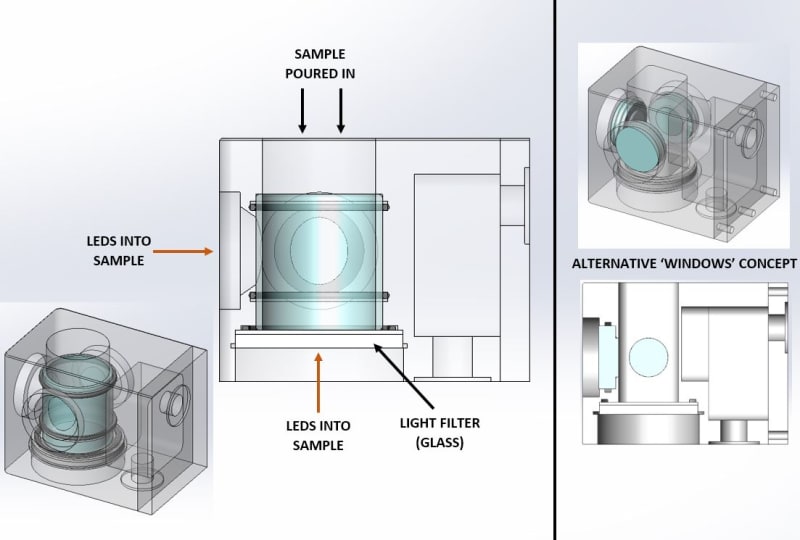
I'm designing a system where a sea water sample must have its temperature controlled between near its freezing point (-2°C) and +30°C to simulate sea temperatures. To control it, the sample will be in contact with a block, which will be controlled by an external circulating water bath. The image should be useful.

I’m new to the world of temperature control and heat exchange, so please correct me here.

MATERIAL SELECTION:
- I believe thermal conductivity to be the most influential factor, but have read up on heat capacity and a combination of the two – thermal resistivity. Are these other two worth considering here?
- Sea water, therefore, corrosive environment
- SELECTION: It seems aluminiums and coppers are typical used in water cooling system, but the sea water element leads me to the route of bronze, copper-nickel and titanium (based on wiki page, which I now can’t locate). Any experience of material selection?

DESIGN:
- I understand that it would be ideal to have as much of the sample in contact with the heat exchange block, but I must stick with a system using a glass tube as indicated.
- Air-cooled heat sinks have fins – do I want to go down a similar route of maximising surface area of block with water bath flow? I could add a number of drilled holes in that section.
- Should the volume of the water bath chamber be maximised?
- The block itself may be both smaller and larger in terms of volume of material. What pros/cons do they have? A large block would take longer to change temperature surely, meaning I want the block to be as small in volume.
- Worth going down the route of simulations?

Thank you in advance!
 
 https://files.engineering.com/getfile.aspx?folder=efbf8344-fd16-4168-9e0f-03bb79c524ae&file=Heat_Transfer_Question.JPG
Replies continue below

Recommended for you

So you do have a temp controlled bath to supply the clean water side?
I would look into making a chamber from 70/30 Cu-Ni to hold the seawater, then wrap the outside with Cu tube and circulate the water through that coil.
To improve heat transfer the best method is higher flow velocity, but Cu alloy shave serious flow limits.
Ti would be a better material, but fabrication would be much more difficult.
You could solder the Cu tube onto the outside of the CuNi chamber, but Ti would require specialized welding.

= = = = = = = = = = = = = = = = = = = =
P.E. Metallurgy, Plymouth Tube
 
Some detail -- good

Still insufficient -- what is your time constraint, i.e., how long are you allowed to get the water to any given temperature? And why a water bath? That's an additional lag to get the water bath to the desired temperatures.

How much water? More water, more time.

As Ed suggests contact area improves performance; the coil is part of it; circulating the seawater would significantly aid in performance as well.

And yes, you do need to consider thermal mass as well as convection if you're concerned about speed.

TTFN (ta ta for now)
I can do absolutely anything. I'm an expert! faq731-376 forum1529 Entire Forum list
 
So you do have a temp controlled bath to supply the clean water side?
I would look into making a chamber from 70/30 Cu-Ni to hold the seawater, then wrap the outside with Cu tube and circulate the water through that coil.
To improve heat transfer the best method is higher flow velocity, but Cu alloy shave serious flow limits.
Ti would be a better material, but fabrication would be much more difficult.
You could solder the Cu tube onto the outside of the CuNi chamber, but Ti would require specialized welding.

Yes, external temperature-controlled bath flowing through the right-hand side. I've definitely simplified my diagram, but essentially I need a glass tube as shown, with the cooling coming from that water bath section on the right. Therefore, a Cu tube would not work.

What do you mean by 'shave serious flow limits'?

When you say Ti would be better, what properties specifically?
 
Still insufficient -- what is your time constraint, i.e., how long are you allowed to get the water to any given temperature? And why a water bath? That's an additional lag to get the water bath to the desired temperatures.

I'll try and upload a better diagram soon! It'll be in a lab environment where the test will be ongoing, therefore, time constraint isn't massively critical. I don't expect temperature to change in minutes, perhaps an hour or two would be at the user's limit! The tube shown is Ø25mm ID btw.

How much water? More water, more time.

Do you mean seawater sample volume? If so, I'm trying to minimise it as it will not be stirred (circulated).

As Ed suggests contact area improves performance; the coil is part of it; circulating the seawater would significantly aid in performance as well.

So for my example, would drilling a number of holes/adding features in the cooling bath chamber on the right improve performance (by adding surface area between metal block and water flowing through)?

And yes, you do need to consider thermal mass as well as convection if you're concerned about speed.

I'm more concerned with ensuring that the seawater sample will get to the required temperature eventually! Could you elaborate on 'thermal mass as well as convection'? Do you mean mass of the block/should this be minimised? And convection in this example - the flow of the water bath or from the glass tube to the block through the air gap?
 
Why glass?
Why a block design?
The fewer intermediate materials the better the heat transfer.
There should be no air gaps.
With a block design it will likely take hours (>12hr) to reach a new stable temp.

Cu alloy HAVE flow limits. Even with clean pure water flow over 6 ft/sec will accelerate erosion.
Ti would handle a lot more flow, but has fabrication issues.


= = = = = = = = = = = = = = = = = = = =
P.E. Metallurgy, Plymouth Tube
 
How much money are you willing to spend?

> I concur with the helical copper coil brazed to a copper tube for holding the sample
> Cooling water needs to be mixed with glycol to prevent freezing
> Anything exposed to air during the cold cycle will condense moisture from the air, which may cause unintended corrosion
> What is the glass supposed to be doing? It's severely limiting the heat flow to the bottom half of the sample

TTFN (ta ta for now)
I can do absolutely anything. I'm an expert! faq731-376 forum1529 Entire Forum list
 
My apologies, my initial diagram was an early concept simplification - see attached for a better reason for having a glass tube. Essentially, all four bores are for optical purposes, with LEDs behind them. We had a previous product using the glass tube, but without the need for thermal control. Since this glass tube worked previously, we'd like to continue with this path. I've proposed an alternative, using windows - see image. There are optical issues with the windows concept (sample chamber is square in cross section), therefore, it is preferable to go with the glass tube.

Why glass?
Why a block design?
The fewer intermediate materials the better the heat transfer.
There should be no air gaps.
With a block design it will likely take hours (>12hr) to reach a new stable temp.

Cu alloy HAVE flow limits. Even with clean pure water flow over 6 ft/sec will accelerate erosion.
Ti would handle a lot more flow, but has fabrication issues.

Hopefully the attached image will help some of the reasoning for glass/block.

The plan is now to hold the sample within the water bath, meaning it is already at required temp, with the block used to maintain the preset temp.

Good point with the erosion - I expect it to see ~5 litres/min. Titanium would be difficult to machine, but we have the capability.

> I concur with the helical copper coil brazed to a copper tube for holding the sample
> Cooling water needs to be mixed with glycol to prevent freezing
> Anything exposed to air during the cold cycle will condense moisture from the air, which may cause unintended corrosion
> What is the glass supposed to be doing? It's severely limiting the heat flow to the bottom half of the sample

Hopefully the image helps this. The block will sit within an enclosure with humidity sensors so we will see the impact of condensation. And I concur with the glass preventing heat flow, but what suggestions can you provide with the current design to optimise? Or any other concepts that could work?

Heat_Transfer_Question_Part_2_krqyvo.jpg
 
Status
Not open for further replies.
Back
Top